HIGHLANDER Commercial Platform Lift CPL400 CPL600 CPL800 CPL1000 CPL1200 CPL1400 This manual has been provided to assist you with lift installation and operation. For further assistance please contact your authorized Harmar dealer or Harmar’s Technical Service department.
Table of Contents Installing the lift Using the Manual When You Receive the Lift Specifications Safety Code Requirements Site Requirements Required Tools Required Materials Preparing to Install the Lift Controller Harness Connections Installing the platform Installing the outer guard panel Installing the fixed ramp Installing the folding ramp Anchoring the Lift Setting the Limit Switches Verifying Operation of the Lift Manual Override Call-Sends (optional) Top Landing Gate (optional) EMI and Flush Strike
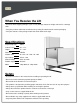
When You Receive the Lift • Check the lift for shipping damage. If you see any damage contact the freight carrier to file a damage claim. • Verify the products match that described on the packing list attached to the exterior packaging. • Verify the contents of the package match that shown below to the right.
Code Requirements Your lift has been designed to meet ASME A18.1 section 2 and CSA B44/ASME A17.5, with the addition of certain options. Code requirements for Vertical Platform lifts vary depending on location. It is the installers responsibility to contact their local code enforcement office and determine all of the regulations they are subject to. You must do this before installing the Vertical Platform Lift. Site Requirements • The lift will require a 115vac 20amp grounded circuit.
Preparing to Install the Lift Final Site Inspection Verify the surface the lift will mount to is smooth and level. This surface must be made from 3,500 psi reinforced concrete with a minimum thickness of 4”. Verify that there is enough space for the lifts foot print. Be sure to include space neccesary for platform. Caution: Verify that the running clearance around the lift complies with any codes for your area.
Installing the Platform Step 1 The mounting bolts, nuts and spacers that secure the platform to the lift carriage are packaged in the small parts box. Begin by locating these pieces and setting aside. Step 2 Position the platform by aligning the support legs with the carriage flanges that protrude from the front cover. Step 3 Align the four mounting holes and insert a ½” x 3” bolt into each hole. The upper holes have a spacer that must be placed in between the carriagne flange and platform leg.
Installing the Outer Guard Panels Step 1 Remove the hexbolts on the corners of the platform. Insert the guard panel posts into the pockets in the platform. The smooth side of the guard panels should face in towards the center of the platform. Step 3 Plug in the harness for the platform control box. Secure the harnesses under the clip on top of the carriage flange. If you have a 90 degree exit platform, install the end guard panel using the provided bracket and bolt to inner guard panel.
Installing Auto-folding Ramp (optional) Step 1 Install the ramp roller guide on the side of the lift tower using the screws already installed in the panels. Step 3 Attach the ramp to the pivot tabs using shoulder bolts and locking nuts. Tighten the nuts until they seat against the bolt shoulder. Step 4 Attach the ramp roller arm by bolting it to the underside of the ramp. Step 2 Attach the two ramp pivot tabs to the lower landing sides of the platform.
Anchoring the Lift Anchors Harmar recommends securing the lift using the concrete anchors provided. If you purchase you own floor anchors they must be 3/8” minimum of sufficient length. All four floor anchors must be installed correctly in accordance to their instructions. Step 1 • Position the lift in its final location. • Verify that it is level and perpendicular to its surroundings and all running clearances are the proper dimension. • Shim if necessary.
Setting the Limit Switches Your lift is equipped with upper and lower limit switches. The vertical location of these switches may be adjusted to fit your application. Typically the upper limit switch will need to be adjusted so the platform will stop level with the upper landing. The lower limit will typically not need adjusting. Step 1 Verify the emergency switch is in the ON position. Run the lift in the up direction until the platform floor is level with the upper landing.
Verifying Operation of the Lift Caution: Complete the following section before training the customer to use the lift. Step 1 Run the lift up and down for 5 complete cycles. Hold the direction button down and allow the limit switches to stop the lift. At the top, verify that the platform stops level with the upper landing. At the bottom, verify the access ramp (if equipped) unfolds and rests on the ground. Step 2 Verify the operation of the Emergency stop switch.
Manual Override Call-Sends (optional) Your lift is equipped with a manual handcrank, to be used in the case of a power failure. The optional Call-Send controls are to be used at the upper and/or lower landings to call the platform to you or send it to the other landing. Step 1 Before using the manual handcrank verify that it’s use is required. Check that the emergency stop switch is pulled out. Check that the electrical cord is connected to the supply.
Top Landing Gate (optional) The optional top landing gate is provided with a combination mechanical lock and electric contact (interlock). The interlock: • Prevents the lift from running if the gate is not closed. • Prevents the gate from being opened if the platform is not at the top landing. • Unlocks when the lift is on the upper limit switch. A length of multi‐conductor wire will need to be ran from the bottom of the lift tower up to the landing gate.
EMI and Flush Strike Interlocks (optional) The optional EMI or Flush Strike Interlocks are provided with a combination mechanical lock and electric contact. They are to be used with existing doors. The interlock: • Prevents the lift from running if the door is not closed. • Prevents the door from being opened if the platform is not at the landing. • Unlocks when the lift is on the landing limit switch. 4) Attach door keeper and emergency key plates to hoistway door. .
Platform Gate (optional) The optional platform gate is provided with a combination mechanical lock and electric contact (interlock). The interlock: • Prevents the lift from running if the gate is not closed. • Prevents the gate from being opened if the platform is not at the bottom landing. • Unlocks when the lift is on the lower limit switch. A crescent shaped key is provided to manually unlock the gate during installation.
Fascia Panel (optional) A fascia panel provides a smooth surface for the platform edge to run against to prevent any shear or obstruction hazards and must be utilized. A running clearance of no more than 3/4” and no less than 3/8” must be maintained between the edge of the platform and the fascia panel.
Commercial Platform Lift - Owners Section LRead the manual thoroughly before operating the lift.
Congratulations on the purchase of your Harmar Vertical Platform Lift. This lift has been engineered to provide trouble free service for many, many years. Please read this manual completely before operating your lift. Safety • Do not exceed the maximum payload capacity of 750 lbs. • Do not ride on the lift until it is anchored in place. • This product is designed only for lifting people and wheel chairs. Do not use it for any other purpose.
Controls Emergency Stop In an emergency push this red button to stop the lift. Turn the button clockwise to run. Up Controls upward movement of lift platform. To move platform up, depress and hold the upper half of the rocker switch. To cease movement, release switch. Down Controls downward movement of lift platform. To move platform down, depress and hold the lower half of the rocker switch. To cease movement, release switch.
Operating the Lift Step 1 - Up Drive onto and stop in the middle of the platform. Apply the brakes of your chair or scooter. Step 2 Verify that the emergency stop button is not activated by giving it a quick turn clockwies. Step 3 Press and hold the UP rocker. The lift will move in the up direction and stop when it reaches the upper landing. Warning: Always verify the lift’s platform has stopped level with the upper landing. If not contact your Harmar Dealer for assistance.
Step 1 - Down Drive onto and stop in the middle of the platform. Apply the brakes of your chair or scooter. Step 2 Verify that the emergency stop button is not activated by giving it a quick turn clockwise. Step 3 Press and hold the DOWN rocker. The lift will move in the down direction and stop when it reaches the lower landing. Warning: Always verify the lift’s access ramp unfolds fully and rests on the ground. If not contact your Harmar Dealer for assistance.
Limited Warranty Certificate 22 Please fill out all fields and return within 10 days of product purchase. Toll-Free Fax: 1-866-234-5680, Online: www.harmar.com or Mail to: Harmar Summit, LLC.