
Manual


Page 4 of 6
4.4 Periodic Inspection
4.4.1 Inspections should be made on a PERIODIC basis in accordance with Table 4-2, “Periodic Inspection.” Evaluation and
resolution of the results of PERIODIC Inspections shall be made by a designated person such that the hoist is maintained in
safe working condition.
4.4.2 For inspections where load suspension parts of the hoist are disassembled, a load test per ANSI/ASME B30.21 must be
performed on the hoist after it is re-assembled and prior to its return to service.
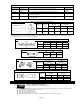
Table 4-2 Periodic Inspection
Requirements of frequent inspection.
Evidence of loose bolts, nuts, or rivets.
Evidence of worn, corroded, cracked, or distorted parts such as suspension housing, chain attachments, yokes,
suspension bolts, shafts, gears, bearings, pins, rollers and locking and clamping devices.
Evidence of damage to hook retaining nuts or collars and pins, and welds or rivets used to secure the retaining members.
Evidence of damage or excessive wear of load sheave.
Evidence of worn, glazed or oil contaminated friction disks; worn pawls, cams or ratchet; corroded, stretched, or broken pawl
springs in brake mechanism.
Evidence of damage to supporting structure.
Function label on hoist for legibility.
Warning label properly attached to the hoist and legible (see Section 7, Fig. No. 37).
End connections of load chain stopper link.
4.5 Inspection Methods and Criteria
4.5.1 This section covers the inspection of specific items. The list of items in this section is based on those listed in ANSI/ASME
B30.21 for the Frequent and Periodic Inspection.
4.5.2 Frequent Inspection - Not intended to involve disassembly of the hoist. Disassembly for further inspection would be required
if only if frequent inspection results so indicate. Disassembly and further inspection should only be performed by a qualified
person trained in the disassembly and re-assembly of the hoist.
4.5.3 Periodic Inspection - Disassembly of the hoist is required. Disassembly should only be performed by a qualified person
trained in the disassembly and re-assembly of the hoist.
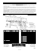
Table 4-3 Hoist Inspection Methods and Criteria
Item Method Criteria Action
Functional
operating
mechanisms.
Visual, Auditory Mechanisms should be properly adjusted and should not produce unusual sounds
when operated. Components should not be deformed, scarred or show significant
wear.
Repair or replace
as required.
Braking System
– Components
Visual Brake Pawl, Pawl Shaft, Pawl Spring, Friction Disc and Ratchet Disc should not
be deformed scarred or show significant wear.
Replace
Braking System
– Friction Plate
Visual, Measure The surface of the friction plate should be free of grease, oil, scars, gouges and
wear and have uniform thickness. The thickness of both plates together should
not be less than the discard value listed in Table 4-6.
Replace
Housing
Mechanical and
Lifting System –
Components
Visual, Auditory,
Function
Hoist components including load blocks, suspension housing, chain attachments,
clevises, yokes, suspension bolts, shafts, gears, bearings, pins and rollers should
be free of cracks, distortion, significant wear and corrosion. Evidence of same
can be detected visually or via detection of unusual sounds during operation.
Replace.
Hooks –
Condition
Visual Should be free of gouges, dents, weld splatter, significant corrosion, twists,
deformations, significant wear, dirt and grime. Hook should swivel freely.
Replace.
Hooks – Fretting
wear
Measure The "u" and "t" dimensions should not be less than the discard value listed in
Table 4-4.
Replace.
Hooks – Stretch Measure The "k" dimension should not be greater than 1.05 times that measured and
recorded at the time of purchase (See Section 3.1). If recorded "k" values are not
available for hooks when new, use nominal "k" values from Table 4-4.
Replace.
Hooks – Hook
Latches
Visual, Function Latch should not be deformed. Attachment of latch to hook should not be loose
or stiff. Latch spring should not be missing and should not be weak.
Replace.
Hooks – Yoke
Assembly
Visual Should be free of significant rust, weld splatter, nicks, gouges. Holes should not
be elongated, fasteners should not be loose (Refer to figure in Section 7.0), and
there should be no gap between mating parts.
Torque or
replace as
required.
Yoke – Hole
Deformation
Visual, Measure The "d" dimension of the chain pin hole and "D" dimension of the top pin hole
should not be greater than the discard value listed in Table 4-7.
Replace Hook
Set
Chain Pin & Top
Pin – Deformation
Visual, Measure The chain pin and top pin should be free of scars or significant deformation. The
"d" and "D" dimension should not be less than discard value listed in Table 4-8.
Replace
Load Chain –
Surface
Condition,
Lubrication
Visual Should be free of gouges, nicks, dents, weld splatter and corrosion. Links should
not be deformed, and should not show signs of abrasion. Surfaces where links
bear on one another should be free of significant wear. Entire surface should be
coated with lubricant and should be free of dirt and grime.
Replace (only
with load chain
listed in parts
list).
Load Chain –
Pitch and Wire
Diameter
Measure The "P" dimension should not be greater than discard value listed in Table 4-5.
The "d" dimension should not be less than discard value listed in Table 4-5.
Replace (see
above). Inspect
load sheave.