EFFECTIVE: June 24, 2009 Owner’s Manual ELECTRIC CHAIN HOIST ER and NER SERIES 1/8 Ton through 5 Ton Capacity Code, Lot and Serial Number WARNING This equipment should not be installed, operated or maintained by any person who has not read and understood all the contents of this manual. Failure to read and comply with the contents of this manual can result in serious bodily injury or death, and/or property damage.
Table of Contents Section 1.0 2.0 3.0 4.0 5.0 Page Number Important Information and Warnings ……………………………………………………………………… 4 1.1 Terms and Summary 1.2 Warning Tags and Labels Technical Information…………………………………………………………………………….…………. 8 2.1 Specifications 2.2 Dimensions 2.3 Hot Metal Applications Preoperational Procedures ……………………………………………………………………………… 12 3.1 Fill Gear Box with Oil 3.2 Chain 3.3 Mounting Location 3.4 Mounting the Hoist 3.5 Electrical Connections 3.
Section 6.0 Page Number Maintenance & Handling …………………………………………………………………………………. 29 6.1 Count/Hour Meter 6.2 Lubrication 6.3 Motor Brake 6.4 Load Chain 6.5 Friction Clutch and Mechanical Load Brake with Friction Clutch 6.6 Storage 6.7 Outdoor Installation 7.0 Troubleshooting …………………………………………………………………………………………… 35 8.0 Material Safety Data Sheets ……………………………………………………………………………… 38 8.1 ER Model Gear Box Oil 8.2 NER Model Gear Box Oil 8.3 (N)ER Model Load Chain Grease 9.
1.0 Important Information and Warnings 1.1 Terms and Summary This manual provides important information for personnel involved with the installation, operation and maintenance of this product. Although you may be familiar with this or similar equipment, it is strongly recommended that you read this manual before installing, operating or maintaining the product. Danger, Warning, Caution and Notice Throughout this manual there are steps and procedures that can present hazardous situations.
WARNING Equipment described herein is not designed for and MUST NOT be used for lifting, supporting, or transporting people, or for lifting or supporting loads over people. Equipment described herein should not be used in conjunction with other equipment unless necessary and/or required safety devices applicable to the system, crane, or application are installed by the system designer, system manufacturer, crane manufacturer, installer, or user.
DANGER HAZARDOUS VOLTAGES ARE PRESENT IN THE CONTROL BOX, OTHER ELECTRICAL COMPONENTS, AND CONNECTIONS BETWEEN THESE COMPONENTS. Before performing ANY mechanical or electrical maintenance on the equipment, de-energize (disconnect) the main switch supplying power to the equipment; and lock and tag the main switch in the de-energized position. Refer to ANSI Z244.1, “Personnel Protection – Lockout/Tagout of Energy Sources”. Only trained and competent personnel should inspect and repair this equipment.
1.2 Warning Tags and Labels The warning tag illustrated below in Figure 1-1 is supplied with each hoist shipped from the factory. If the tag is not attached to your hoist’s pendant cord, order a tag from your dealer and install it. Read and obey all warnings attached to this hoist. Tag is not shown actual size.
2.0 Technical Information 2.1 Specifications 2.1.1 Product Code 2.1.2 ER and NER Models - Harrington ER series hoist are available in two versions, the ER and NER. These two versions are equipped with different options as standard equipment. The NER has a friction clutch mechanism that provides over winding protection. The ER has a mechanical load brake/friction clutch combination and an electronic count/hour meter in the control circuit.
Table 2-1 Hoist Specifications Motor Capacity DUAL SPEED SINGLE SPEED (Ton) Code Current Draw Lifting Speed Output (ft/min) (Hp) (amps) 208V or 230V 460V Load Chain Wire Diameter (mm) x Chain Fall Lines Load Sheave Pockets Net Weight (lbs) Weight for One Addnl. FT. of Lift (lbs) 1/8 (N)ER001H 57 0.75 4.2 2.1 5.0 x 1 5 68 0.37 1/4 (N)ER003S 39 0.75 4.2 2.1 5.0 x 1 5 68 0.37 1/4 (N)ER003H 60 1.2 5.7 2.9 6.3 x 1 5 84 0.57 1/2 (N)ER005L 15 0.75 4.2 2.1 6.
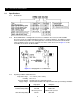
2.2 Dimensions Figure 2-2 Hoist Dimensions (See Table 2-3) Table 2-2 Hook Dimension* T = Top Hook B = Bottom Hook Units = inch Capacity Code Hook a b c d e g 001H, 003S, 003H, 005L, 005S T 1.1 0.7 0.9 0.7 1.4 1.1 B 1.1 0.7 0.9 0.7 1.4 0.9 010L, 010M, 010S T&B 1.4 0.9 1.2 0.9 1.7 1.2 T 1.9 1.1 1.6 1.1 2.0 1.5 B 1.7 1.0 1.4 1.0 1.9 1.3 T&B 1.9 1.1 1.6 1.1 2.0 1.5 T 2.2 1.4 1.9 1.4 2.4 1.7 B 2.0 1.2 1.7 1.2 2.1 1.6 030C, 030L, 030S T&B 2.
Table 2-3 Hoist Dimensions Hoist Code Minimum Headroom: C L* a b d e g h i (ft) (in) (in) (in) (in) (in) (in) (in) (in) 13.8 7.2 21.1 13.0 10.4 10.7 0.9 4.0 3.9 (N)ER003S 13.8 7.2 21.1 13.0 10.4 10.7 0.9 4.0 3.9 (N)ER003H 14.6 7.2 21.9 13.8 10.8 11.1 0.9 4.7 4.1 (N)ER005L 14.0 7.2 21.1 13.0 10.4 10.7 0.9 4.0 3.9 (N)ER005S 14.6 7.2 21.9 13.8 10.8 11.1 0.9 4.7 4.1 (N)ER010L 16.1 7.2 21.9 13.8 10.8 11.1 1.2 4.7 4.1 NER010M 16.1 7.
3.0 Preoperational Procedures 3.1 Fill Gear Box with Oil CAUTION 3.1.1 The ER (with mechanical load brake/friction clutch) uses different gear oil than the NER (with friction clutch). DO NOT use any oil or quantity other than that listed below. 3.1.2 For a new hoist the correct quantity and type of oil is supplied with the hoist in separate container(s). Remove the fill plug from the top of the hoist and connect the flexible pour tube to the oil container.
Figure 3-2 Chain Component Arrangement for Hoists with Upper Limit Switch Only. Figure 3-3 Chain Component Arrangement for Hoists with Optional Upper and Lower Limit Switch.
Table 3-2 Chain Stopper Placement Capacity Code Without Chain Container With Chain Container 001HD, dual speed with optional upper/lower limit switch 25th link from the free end 3rd link from the free end 001H, 003S, 003H, 005L, 005S, 010L, 010M, 010S, 015S, 020L, 020M, 030C 15th link from the free end 3rd link from the free end 020S, 025S, 030L, 030S, 050L 13th link from the free end 3rd link from the free end Figure 3-4 Attachment of Chain to Hoist Body – No Chain Container 3.2.3 3.2.
Figure 3-5 Attachment of Chain Container to Hoist Body 3.2.5 3.2.6 When using an optional steel chain container, refer to the assembly drawing and instructions provided with the container for correct assembly and attachment. WARNING Verify that the load chain is not twisted or tangled prior to operating the hoist. Make sure the bottom hook on 3 and 5 Ton double fall models is not capsized. See Figures 3-6 and 37. Correct all chain irregularities before conducting the first hoist operation.
Figure 3-7 Capsized Hook and Chain – 3 and 5 Ton Double Fall Models 3.3 Mounting Location 3.3.1 3.3.2 3.4 3.5 WARNING Prior to mounting the hoist ensure that the suspension and the supporting structure are adequate to support the hoist and its loads. If necessary consult a professional that is qualified to evaluate the adequacy of the suspension location and its supporting structure. NOTICE See Section 6.7 for outdoor installation considerations. Mounting the Hoist 3.4.
Power Supply Cable - Hoist Connection The Power Supply Cable connects to the hoist via a 4-pin (4P) plug and socket. Make this connection as follows: Refer to Figure 3-8. Insert the 4P plug of the Power Supply Cable into the 4P Socket on the hoist and hand tighten the screw coupling. Install the Cable Support Arm (pre-installed on the Power Supply Cable) on to the Socket Holder using the pre-installed Machine Screws and Lock Washers. Use care to avoid twisting or kinking the Power Supply Cable.
3.5.7 3.6 DANGER Grounding - An improper or insufficient ground connection creates an electrical shock hazard when touching any part of the hoist or trolley. In the Power Supply Cable the ground wire will be either Green with Yellow stripe or solid Green. It should always be connected to a suitable ground connection. Do not paint the trolley wheel running surfaces of the beam as this can affect grounding. Preoperational Checks and Trial Operation 3.6.
4.0 Operation 4.1 Introduction DANGER DO NOT WALK UNDER A SUSPENDED LOAD WARNING HOIST OPERATORS SHALL BE REQUIRED TO READ THE OPERATION SECTION OF THIS MANUAL, THE WARNINGS CONTAINED IN THIS MANUAL, INSTRUCTION AND WARNING LABELS ON THE HOIST OR LIFTING SYSTEM, AND THE OPERATION SECTIONS OF ANSI/ASME B30.16 and ANSI/ASME B30.10. THE OPERATOR SHALL ALSO BE REQUIRED TO BE FAMILIAR WITH THE HOIST AND HOIST CONTROLS BEFORE BEING AUTHORIZED TO OPERATE THE HOIST OR LIFTING SYSTEM.
The operation of an overhead hoist involves more than activating the hoist’s controls. Per the ANSI/ASME B30 standards, the use of an overhead hoist is subject to certain hazards that cannot be mitigated by engineered features, but only by the exercise of intelligence, care, common sense, and experience in anticipating the effects and results of activating the hoist’s controls.
CAUTION Improper operation of a hoist can create a potentially hazardous situation which, if not avoided, could result in minor or moderate injury, or property damage. To avoid such a potentially hazardous situation THE OPERATOR SHALL: • Maintain a firm footing or be otherwise secured when operating the hoist. • Use the hoist manufacturer’s recommended parts when repairing the unit. • Check brake function by tensioning the hoist prior to each lift operation.
5.0 Inspection 5.1 General 5.1.1 5.2 The inspection procedure herein is based on ANSI/ASME B30.16. The following definitions are from ANSI/ASME B30.16 and pertain to the inspection procedure below. Designated Person – a person selected or assigned as being competent to perform the specific duties to which he/she is assigned.
5.3 Frequent Inspection 5.3.1 Inspections should be made on a FREQUENT basis in accordance with Table 5-1, “Frequent Inspection.” Included in these FREQUENT Inspections are observations made during operation for any defects or damage that might appear between Periodic Inspections. Evaluation and resolution of the results of FREQUENT Inspections shall be made by a designated person such that the hoist is maintained in safe working condition.
5.5 Occasionally Used Hoists 5.5.1 5.6 5.7 Hoists that are used infrequently shall be inspected as follows prior to placing in service: Hoist Idle More Than 1 Month, Less Than 1 Year: Inspect per FREQUENT Inspection criteria in Section 5.3. Hoist Idle More Than 1 Year: Inspect per PERIODIC Inspection criteria in Section 5.4. Inspection Records 5.6.
Table 5-3 Hoist Inspection Methods and Criteria Item Method Criteria Action Hooks - Yoke Assembly Visual Should be free of significant rust, weld splatter, nicks, gouges. Holes should not be elongated, fasteners should not be loose, and there should be no gap between mating parts. Tighten or replace as required. Hooks - Swivel Bearing Visual, Function Bearing parts and surfaces should not show significant wear, and should be free of dirt, grime and deformations.
Table 5-3 Hoist Inspection Methods and Criteria Item Method Criteria Action Bolts, Nuts and Rivets Visual, Check with Proper Tool Bolts, nuts and rivets should not be loose. Tighten or replace as required. Motor Brake Measure, Visual Motor brake gap should be adjusted to the distance shown in Table 6-4 before measuring the brake wear. Brake lining dimension “A” should not be less than discard value listed in Table 5-6. Refer to Section 6.
Table 5-4 Top Hook & Bottom Hook Dimensions “k” Measured When New: Top: _________________________ Bottom: ______________________ "u" Dimension inch (mm) "t" Dimension inch (mm) Nominal "k" Dimension* inch (mm) Standard Discard Standard Discard 001H, 003S, 003H, 005L, 005S 1.65 (42) 0.93 (23.5) 0.83 (21) 0.69 (17.5) 0.63 (16) 010L, 010M, 010S 1.97 (50) 1.22 (31) 1.10 (28) 0.89 (22.5) 0.79 (20) 015S 2.36 (60) 1.44 (36.5) 1.30 (33) 1.04 (26.5) 0.94 (24) 2.46 (62.5) 1.57 (40) 1.
Table 5-6 Motor Brake Wear Dimensions NOTICE Brake must be properly adjusted before measuring "A". See Section 6.3 "A" Dimension - inch (mm) Capacity Code Single Speed Dual Speed Standard Discard Standard Discard 0.67 (17) 0.61 (15.5) 0.67 (17) 0.61 (15.5) 003H, 005S, 010L, 010M 0.85 (21.5) 0.79 (20) 0.85 (21.5) 0.79 (20) 010S, 015S, 020L, 020M, 030C 0.89 (22.5) 0.83 (21) 1.06 (27) 1.00 (25.5) 0.83 (21) 0.77 (19.5) 1.54 (39) 1.48 (37.
6.0 Maintenance and Handling 6.1 Count/Hour Meter 6.1.1 The Count/Hour (C/H) Meter located in on the electrical control panel records the hoist's on time and number of starts. To view the two values press the button on the C/H Meter one time. The display will first show an "H" and a 4 digit number which is the hoist's total on time (up and down) in hours. After 3 seconds the display will automatically change to a 6 digit number which is the number of starts of the hoist's down contactor.
6.2 Lubrication 6.2.1 Load Chain For longer life, the load chain should be lubricated. The load chain lubrication should be accomplished after cleaning the load chain with an acid free cleaning solution. Apply Harrington lubricating grease (Part No. ER1BS1951) or an equivalent to industrial general lithium grease, NLGI No. 0, to the bearing surfaces of the load chain links as indicated by the shaded areas in Figure 6-2.
Change gear oil at least once every 5 years. The oil should be changed more frequently depending on the hoist's usage and operating environment. Refer to Section 6.1. Refer to Figure 3-1 and Table 3-1 to change the gear oil, remove both fill and drain plugs and allow the old oil drain completely. Replace the drain plug and refill the gear case with the correct quantity of new oil or until the oil level is within the range shown in Table 6-3.
1) Bend the tab of the Lock Washer away from the Adjusting Nut so that the Adjusting Nut can be rotated. 2) Using a spanner wrench and a feeler gauge, rotate the Adjusting Nut to attain the proper Brake Gap per Table 6-4. 3) After the Brake Gap is set, secure the Adjusting Nut by bending one of the tabs of the Lock Washer into a slot in the Adjusting Nut. If necessary rotate the Adjusting Nut clockwise (tightening) to line up the tab with the slot.
6.3.5 6.4 Motor Brake Unit Installation - After the brake is properly adjusted and inspected, carefully replace the motor brake unit back into the hoist. Be sure to reseal the Motor Cover to motor frame surface using a small bead of liquid (hi-temperature) sealant. Refer to Section 6.3.2 and reassemble the parts in reverse order of removal. Load Chain 6.4.1 Lubrication and Cleaning – refer to Section 6.2. 6.4.
Figure 6-4 Chain Replacement 6.6 6.7 Storage 6.6.1 ER models with vented oil cap assemblies should be stored with the cap oriented up to prevent oil leakage. 6.6.2 The storage location should be clean and dry. Outdoor Installation 6.7.1 For hoist installations that are outdoors, the hoist should be covered when not in use. 6.7.2 Possibility of corrosion on components of the hoist increases for installations where salt air and high humidity are present.
7.0 Troubleshooting WARNING HAZARDOUS VOLTAGES ARE PRESENT IN THE HOIST AND IN CONNECTIONS BETWEEN COMPONENTS. Before performing ANY troubleshooting on the equipment, de-energize the supply of electricity to the equipment, and lock and tag the supply device in the de-energized position. Refer to ANSI Z244.1, “Personnel Protection Lockout/Tagout of Energy Sources.” Only Trained and competent personnel should inspect and repair this equipment.
Table 7-1 Troubleshooting Guide Symptom Hoist lifts but will not lower Hoist lowers but will not lift Hoist will not lift rated load or does not have the proper lifting speed Load drifts excessively when hoist is stopped Cause Remedy Down circuit open Check circuit for loose connections. Check down side of limit switch for malfunction. Broken conductor in pendant cord Check the continuity for each conductor in the cable. If one is broken, replace entire cable.
Table 7-1 Troubleshooting Guide Symptom Motor or brake overheating Hoist operates intermittently Cause Remedy Excessive load Reduce load to within rated capacity of hoist. Excessive duty cycle Reduce frequency of lifts. Wrong voltage or frequency Check voltage and frequency of power supply against the rating on the nameplate on the motor. Brake drags Check brake adjustment for proper clearance.
8.0 Material Safety Data Sheets NOTICE The ER and NER hoists are shipped new with the oil for the gear box and the grease for the load chain in separate container(s). In compliance with OSHA regulations, Material Safety Data Sheets (MSDS) have been provided for the gear oil that is provided in this separate container. The ER (with mechanical load brake/friction clutch) uses different gear oil than the NER (with friction clutch). Identify the correct model (refer to Section 2.
ER Model Gear Box Oil Material Safety Data Sheet (MSDS) - continued SECTION III HAZARDS IDENTIFICATION EMERGENCY OVERVIEW Warning statement: Caution! Prolonged or repeated contact with skin may cause irritation in some cases. Precautionary Measures: Avoid breathing vapor and mist. Keep container closed. Avoid contact with eyes, skin, and clothing. Wash thoroughly after handling. Keep away from heat. Potential health effect: Eyes: May cause minor irritation. Skin: May cause minimal skin irritation.
ER Model Gear Box Oil Material Safety Data Sheet (MSDS) - continued SECTION VI ACCIDENTAL RELEASE MEASURES Procedures in Case of Accidental Release, Breakage, or Leakage: Stop the source of the leak or release. Clean up releases as soon as possible. Contain liquid to prevent further contamination of soil, surface water or groundwater. Clean up small spills using appropriate techniques such as absorbent materials or pumping. Where feasible and appropriate, remove contaminated soil.
ER Model Gear Box Oil Material Safety Data Sheet (MSDS) - continued SECTION X STABILITY AND REACTIVITY Stability: Condition to Avoid: Incompatibility (materials to avoid): Hazardous Polymerization: Thermal decomposition: SECTION XI Stable See the Handling and Storage section for further details. Acids. Oxidizing agents. Halogens and halogenated compounds. Will not occur. Smoke, carbon monoxide, aldehydes and other products of incomplete combustion.
ER Model Gear Box Oil Material Safety Data Sheet (MSDS) - continued SECTION XV REGULATION INFORMATION The U.S. TSCA inventory: The EC EINECS inventory: The CANADA DSL inventory: The AUSTRALIA AICS inventory: The KOREA TCCL inventory: The PHILIPPINE PICCS inventory: SECTION XVI All components of this material are on the US TSCA inventory. All components of this material are on the EC EINECS inventory. May require notification before sale in CANADA. May require notification before sale in AUSTRALIA.
8.2 NER Model Gear Box Oil Material Safety Data Sheet (MSDS) SECTION I EMERGENCY TELEPHONE NUMBER 03-3502-9161 MANUFACTURER’S NAME Nippon Oil Co., Ltd. TELEPHONE NUMBER FOR INFORMATION 03-3502-1111 ADDRESS 3-12, Nishi Shimbashi 1-chome, Nimato-ku, Tokyo, 105 Japan DATE PREPARED Oct. 14, 1992 SIGNATURE OF PREPARER Signature on file at Harrington Hoists, Inc.
NER Model Gear Box Oil Material Safety Data Sheet (MSDS) - continued SECTION V HEALTH HAZARD INFORMATION SYMPTOMS OF OVEREXPOSURE FOR EACH POTENTIAL ROUTE OF EXPOSURE Inhalation: Not expected to be acutely toxic by inhalation. Skin: Expected to cause no more than minor skin irritation, but prolonged or frequently repeated skin contact may be harmful. Eyes: Expected to cause no more than minor irritation. Absorption through skin: Ingestion: No information is available.
NER Model Gear Box Oil Material Safety Data Sheet (MSDS) - continued SECTION X REQUIREMENTS FOR TRANSPORTATION, HANDLING, AND STORAGE Minimum feasible handling temperatures should be maintained. Periods of exposure to high temperatures should be minimized. Water contamination should be avoided. SECTION XI SPILL, LEAK, AND DISPOSAL PROCEDURES PROCEDURES IN CASE OF BREAKAGE OR LEAKAGE Wipe up or absorb on suitable material and shovel up.
8.3 (N)ER Model Load Chain Grease Material Safety Data Sheet (MSDS) Effective date: November 9, 1999 SECTION 1. MSDS No.
(N)ER Model Load Chain Grease Material Safety Data Sheet (MSDS) - continued SECTION 3. HAZARDS IDENTIFICATION EMERGENCY OVERVIEW Warning statement: Caution! Prolonged or repeated contact with skin may cause irritation in some cases. Precautionary Measures: Avoid breathing vapor and mist. Keep container closed. Avoid contact with eyes, skin, and clothing. Wash thoroughly after handling. Keep away from heat. Potential health effect: Eyes: May cause minor irritation.
(N)ER Model Load Chain Grease Material Safety Data Sheet (MSDS) - continued SECTION 6. ACCIDENTAL RELEASE MEASURES Procedures in Case of Accidental Release, Breakage, or Leakage: Stop the source of the leak or release. Clean up releases as soon as possible. Contain liquid to prevent further contamination of soil, surface water or groundwater. Clean up small spills using appropriate techniques such as absorbent materials or pumping. Where feasible and appropriate, remove contaminated soil.
(N)ER Model Load Chain Grease Material Safety Data Sheet (MSDS) - continued SECTION 10. STABILITY AND REACTIVITY Stability: Condition to Avoid: Incompatibility (materials to avoid): Hazardous Polymerization: Thermal decomposition: SECTION 11. Stable See the Handling and Storage section for further details. Acids. Oxidizing agents. Halogens and halogenated compounds. Will not occur. Smoke, carbon monoxide, aldehydes and other products of incomplete combustion.
(N)ER Model Load Chain Grease Material Safety Data Sheet (MSDS) - continued SECTION 15. REGULATION INFORMATION The U.S. TSCA inventory: The EC EINECS inventory: The CANADA DSL inventory: All components of this material are on the US TSCA inventory. May require notification before sale in US. No data available. All components of this material are on the EC EINECS inventory. May require notification before sale in EC. No data available. Some components of this material is on the EC ELINCS inventory.
9.0 Warranty All products sold by Harrington Hoists, Inc.
This Page Intentionally Left Blank 52
10.0 Parts List When ordering Parts, please provide the Hoist code number, lot number and serial number located on the Hoist nameplate (see fig. below). Reminder: Per sections 1.1 and 3.6.4 to aid in ordering Parts and Product Support, record the Hoist code number, lot number and serial number in the space provided on the cover of this manual. ER/NER Series Nameplate The parts list is arranged into the following sections: Section Page 10.1 Housing and Motor Parts……………………………………………….…………………………….. 54 10.
10.
Figure Part Name No.
Part Name Motor Frame with Stator 208-230/460V-3-60 Parts Per 001H Hoist 003S 005L 003H 005S 010L S 1 A1KHM03S5A1 A1KHM05S5A1 D 1 A1KHM03B5A1 A1KHM05B5A1 S 1 A1KHA03S5A1 A1KHA05S5A1 D 1 A1KHA03B5A1 A1KHA05B5A1 24 Motor Frame with Stator 575V-3-60 010M A1KHM10E5A1 010S 015S 020L A1KHM10S5A1 020M 030C A1KHM20E5A1 A1KHM10B5A1 A1CKK10E5A1 A1KHA10S5A1 A1CKK20E5A1 A1KHA10B5A1 020S 025S 030L 030S A1KHM20S5A1 A1KHM- A1KHM30S5A1 20S5A1 A1KHM20B5A1 A1KHM- A1KHM30B5A1 20B5A1
Figure No.
10.
Figure No.
22 23 24 Part Name Gear Plate Spring Washer Socket Bolt 60 Ball Bearing 25 26 27 (Needle Bearing for 003S and 005L) Parts Per 001H Hoist 005L F, S 1 M, S 1 ER1BC9261 F, D 1 ER1BC9261 M, D 1 3 M, S 3 9012709 F, D 3 9012709 M, D 3 F, S 3 M, S 3 90912138 F, D 3 90912138 M, D 3 F, S 2 M, S 2 F, D 2 M, D 2 003H 005S ER1BC9261 F, S 9012709 90912138 ER1BC-9265 ER1BC9265 ER1BC9265 F, S 1 M, S 1 F, D 1 M, D 1 M, S 1 ER1BC9268 F, D 1 ER1BC9268 M, D
Figure No.
10.
Figure No.
Part Name Parts Per 001H Hoist 003S 005L 003H 005S 010L 010M 010S 015S 020L 020M 030C 020S 025S 030L 030S 050L 23 Body Protector 1 ER1FR9055 24 Socket Bolt 2 9091272 25 Spring Washer 2 9012711 26 Bottom Hook Complete Set 1 Bottom Hook Assembly 1 27 28 Hook Latch Assembly ER1BH- ER1BS- ER1CS- ER1CH- ER1CS1011 1011 1011 1011 1011 ER1DS1011 ER1DM1011 ER1ES1011 ER1DR ER1ES- ER1EM-1011 1011 1011 ER1FS1011 ER1FS -2011 1 ER1BS1002 ER1DS1002 ER1DM1002 ER1ES1002 ER1FR
This Page Intentionally Left Blank 10.
10.
Fig No Part Name Parts Per 001H Hoist 003S 1 Chain Guide A U 1 ER1BS9331 2 Chain Guide AL U/L 1 ER1BS9330 3 Guide Roller 1 4 Roller Pin 1 005L ER1BL9331 ER1BL9330 003H 005S 010L 010M ER1CS1331 ER1CL1331 ER1CS9330 ER1CL9330 ES403005S ER1CS9334 010S ER1DS1331 ER1DS9330 ER1DS9333 ER1DS9334 015S 020L 020M 030C ER1DL1331 ER1DL9330 ER1DL9333 ER1DL9334 020S 025S ER1ES- ER1EM9331 9331 ER1ES- ER1EM9330 9330 ER1EM9333 030L 030S ER1FS9331 ER1FS9330 ER1FS9333 Limit Lever S U
10.
Fig No Part Name Parts Per 001H Hoist 005S 010L 010M 1 ER1BS1551 1 ER1BS2551 2 Socket Bolt 3 Spring Washer 3 4 Plate 1 3 Plate Screw 6 Hinge 7 Hinge Screw 2 8 Mach. Screw w/Spring Washer 2 9 Bushing 1 010S 015S 020L ER1CB9441 ER1DB9441 M 1 ER1CS9442 ER1ES9442 ER1BS9443 E6F151003 ECP99JBAA ECP99JBAB ECP91CHAB ECP91CHAB 1 MS555010 1 ECP1306AA D 2 S 2 69 14 Mach. Screw w/Spring Washer 15 Mach.
10.
Fig No Part Name Parts Per 001H Hoist 003S 005L 003H 005S 010L 010M 010S 015S 020L 020M 030C 020S 025S 030L 030S 1 Socket Holder 1 ER1BS9511 2 Socket Holder Packing 1 ER1BS9512 3 Machine Screw with Spring Washer 4 ES656003 4 Socket 4P Assembly 1 ER1BS1523 ER1ES1523 5 Socket 5P Assembly S 1 ER1BS1564 ER1ES1564 D 1 ER1BB1564 ER1EB1564 6 Flat Head Tapping Machine Screw 8 7 Power Supply Cable 4C Complete Set 1 ER1BS1521 ER1ES1521 8 Power Supply Cable 4C 1
www.harringtonhoists.com Harrington Hoists, Inc. 401 West End Avenue Manheim, PA 17545-1703 Phone: 717-665-2000 Toll Free: 800-233-3010 Fax: 717-665-2861 Harrington Hoists – Western Division 2341 Pomona Rd.