EFFECTIVE: APRIL 2, 2009 Owner’s Manual LOAD LIMITER for ER2 and NER2 SERIES ELECTRIC CHAIN HOIST 1/8 Ton through 5 Ton Capacity WARNING This equipment should not be installed, operated or maintained by any person who has not read and understood all the contents of this manual. Failure to read and comply with the contents of this manual can result in serious bodily injury or death, and/or property damage.
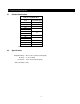
Table of Contents Section 1.0 2.0 3.0 4.0 5.0 6.0 Page Number Important Information and Warnings ............................................................................. 3 1.1 Terms and Summary 1.2 Product Overview Technical Information .................................................................................................... 5 2.1 Product Code 2.2 Specifications 2.3 Dimensions 2.4 Principle of Operation 2.5 Electrical Circuit Installation ................................
1.0 Important Information and Warnings 1.1 Terms and Summary 1.1.1 Definition of Terms This manual provides important information for personnel involved with the installation, operation and maintenance of this product. Although you may be familiar with this or similar equipment, it is strongly recommended that you read this manual before installing, operating or maintaining the product.
1.2 Product Overview The product covered by this manual is Harrington’s Load Limiter (LL) for use with Harrington’s ER2/NER2 Series of electric chain hoists. The LL is an optional accessory that employs a load sensing device and electric switch. Actuation causes the hoist’s lifting circuit to be disabled, while still allowing the hoist to be used in the lower mode. The purpose of the LL is to protect the hoist from damage associated with lifting loads that exceed the hoist’s capacity.
2.0 Technical Information 2.1 Product Identification Table 2-1 LL Identification Hoist Capacity Code* Load Limiter Type 001H 01H 003S 03S 003H 03H 005L 005S 010L 010S 015S 020L 020S 05S 10S 15M 20S 025S 25M 030C 30S 050L 50R *Refer to ER2, NER2 Owner’s Manual. 2.
2.3 Dimensions 2.3.1 Load Limiter Table 2-2 Load Limiter Dimensions Load Limiter Type Dimensions (in) Weight (lb) 01H 03S 03H 05S 10S 15M 20S 25M 30S 50R a 0.94 0.39 0.47 b 0.83 0.47 0.51 c 7.60 7.81 7.93 d 0.48 0.43 0.51 e 0.43 0.43 0.51 9.26 9.48 6 9.
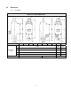
2.3.2 Hoist Figure 2-1 Hoist with LL Table 2-3 Comparison to Standard Model (Without Load Limiter) Additional Weight* (lb) Hoist Cap Capacity (Tons) 001H 1/8 003S 1/4 003H 1/4 005L 005S 010L 010S 015S 020L 020S 1/2 ER2G ER2P ER2M Parallel Susp. ER2M Standard Susp. ER2 +4.32 ER2G ER2P ER2M ER2M Parallel Standard Susp. Susp. +2.05 +0.68 Additional i (in) Additional e (in) +3.98 +3.48 +21.5 +22.5 +7.32 +4.33 +1.97 +0.98 +3.50 1 +4.13 +2.17 +0.59 +3.03 1 1/2 +6.50 +3.
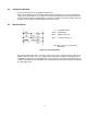
2.4 Principle of Operation Refer to Section 5.0 Parts List for diagram and parts names. When a load is applied between the Plunger and the Casing, the Plunger acts to compress the Belleville Spring. As the spring compresses, the Adjuster mounted on the Plunger Arm moves toward the Switch. If the load is great enough, the spring will compress enough for the Adjuster to actuate the Switch. When the Switch is actuated, it breaks the hoist’s lifting contactor control circuit. 2.
3.0 Installation 3.1 Load Limiter and Suspension Plate 3.1.1 1/8 to 2 1/2 Ton* ER2/NER2 – For installation of the LL, LL Suspension Assembly is used instead of the Standard Suspension Assembly. Install the LL Assembly as follows: *For 025S, follow the instruction in section 3.1.2 when removing the top hook (refer to Figure 3-3). After the removal of the top hook, follow the instruction below (beginning with step 5).* 1) Refer to Fig. 3-1**.
Figure 3-1 Installation of Standard Suspension Assembly for ER2 (1/8 Ton – 3 Ton Except 2 1/2 Ton) **For installation of the LL, LL Suspension Assembly is used instead of the Standard Suspension Assembly shown above.
3.1.2 3 to 5 Ton ER2/NER2 – These applications retain the standard suspension configuration. LL Suspension Plates and LL Connection Yokes are not required. The LL is installed between the hoist’s Connection Yoke and the Load Chain as follows: **For 030C, follow the instruction in section 3.1.1 when removing the top hook (refer to Figure 3-1). After the removal of the top hook, follow the instruction below (beginning with step 9).** 1) Refer to Fig. 3-3* and 3-4.
Figure 3-3 Installation of Standard Suspension Assembly for ER2 (025S and 050L) 12
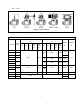
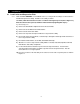
Figure 3-4 Installation location of LL (3 and 5 Ton) 3.2 Socket Frame holder and Load Limit Relay 3.2.1 The Socket Frame Holder L mounts between the Socket Frame Complete Set and the Gear Case. Refer to Figures 3-5 and install as follows: 1) Remove the Socket Frame Complete Set with 4 & 8 Pin Socket Assemblies by: a) Disconnecting the leads coming from the both Socket assemblies. b) Remove the socket frame mounting screws.
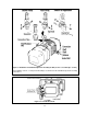
Figure 3-5 Installation of Socket Frame Holder L and Socket Frame Complete Set Figure 3-6 Installation of LL Cable Connector 3.2.2 Install the Load Limiter Relay as follows: 1) Refer to Figure 3-7 for the location of installation. Be sure to review Figure 3-8 for the correct orientation of LL Relay. 2) Refer to Figure 3-9 or 3-10 for the electrical connection of LL Relay.
Model Single Speed B C D E, F Figure 3-7 Placement of LL Relay 15 Dual Speed
Figure 3-8 Correct Orientation of LL Relay Figure 3-9 LL Relay Electrical Connection (Single Speed) 16
Figure 3-10 LL Relay Electrical Connection (Dual Speed) 3.3 Electrical Connections 3.3.1 Refer to wiring diagram for ER2/NER2 71023 and 71024, provided here for basic single and dual speed hoist connections. For other applications, refer to the diagram provided with the hoist or system. Refer to figure 3-13 for installation of LL wiring diagram. 3.3.2 After confirming all electrical connections are made correctly, reassemble the hoist making sure that wires are not pinched.
Figure 3-11 Single Speed Wiring Diagram 18
Figure 3-12 Dual Speed Wiring Diagram 19
Figure 3-13 LL Wiring Diagram Location 3.4 Performance Test Confirm via load testing that the LL actuates within approximately +/- 8% of its setting.
4.0 Adjustment 4.1 General: The general sequence for adjusting is to determine the Static Set Load (SSL), then use the SSL to adjust the Load Limiter (LL). 4.2 Determine Static Set Load 4.2.1 General The general formula for determining the SSL is SSL = RC X SP X f Where RC is Rated Capacity of either LL or hoist. (see sections 4.2.2 or 4.2.3) SP is the percentage of the hoist’s rated capacity at which the LL is to actuate (Factory set at 1.
4.3 Adjust the Load Limiter 4.3.1 Refer to Figure 4-1. 4.3.2 Remove the LL’s case cover. 4.3.3 Loosen the setscrew with a hex wrench and Rotate the adjuster clockwise to obtain a sufficient gap between the adjuster and the electrical switch plunger. 4.3.4 Apply the Static Set Load determined in section 4.2 above. 4.3.5 Rotate the adjuster counter clockwise until the electrical switch is activated or clicks to make contact. A circuit tester may be used to verify the making of contact. 4.3.
This Page Intentionally Left Blank 23
5.0 Parts List 5.1 Internal Parts List Table 5-1 Internal Parts List Fig. No.
Fig. No.
This Page Intentionally Left Blank 26
5.
1 1/2 Ton – 2 Ton ER2M LL Suspension Assembly Figure 5-3 YL2ES1102 2 1/2 Ton ER2M LL Suspension Assembly Figure 5-4 YL2FS1102 28
1/8 Ton – 1/4 Ton S Hook-Mounted ER2, ER2P, ER2G, and ER2M (Parallel) LL Suspension Assembly Figure 5-5 YL2BS1108 1/4 Ton H – 1 Ton Hook-Mounted ER2, ER2P, ER2G, and ER2M (Parallel) LL Suspension Assembly Figure 5-6 YL2CS1108 29
1 1/2 Ton – 2 Ton Hook-Mounted ER2, ER2P, ER2G, and ER2M (Parallel) LL Suspension Assembly Figure 5-7 YL2ES1108 2 1/2 Ton Hook-Mounted ER2, ER2P, ER2G, and ER2M (Parallel) LL Suspension Assembly Figure 5-8 YL2FS1108 30
3 Ton 5 Ton Figure 5-9 Connection Yoke D 31
Table 5-2 Assembly Parts List Suspension Fig. Part Name Qty No.
Suspension Fig. Part Name Qty No. Type* 23 Connection Yoke Bolt B M H/P/G/MP Load Limiter 24 M/H/P/G/MP Assembly 25 Connection Yoke D M/H/P/G/MP Hoist Capacity 001H 003S 003H 005L/005S 010L/010S 020L/020S 025S 030C 050L YL1ES9113 1 1 015S YL1ES9114 YL2BH12 YL2BS120 YL2CH120 YL2CS120 YL2DS120 YL2ES120 YL2ER120 YL2FR120 YL2EM1201 YL2FS1201 01 1 1 1 1 1 1 1 † 1 *Suspension Type: M = ER2M, H = Hook-Mounted ER2, P = ER2P, G = ER2G, MP = ER2M (Parallel) †Supplied with the hoist. 5.
6.0 Warranty All products sold by Harrington Hoists, Inc.
This Page Intentionally Left Blank 35
www.harringtonhoists.com Harrington Hoists, Inc. 401 West End Avenue Manheim, PA 17545 Phone: 717-665-2000 Toll Free: 800-233-3010 Fax: 717-665-2861 Harrington Hoists - Western Division 2341 Pomona Rincon Rd.