EFFECTIVE: EFFECTIVE:May May1,1,2006 2006 Owner’s Manual AIR POWERED CHAIN HOIST TCR SERIES MODEL TCR 10 Ton and 25 Ton Capacity Code, Lot and Serial Number WARNING This equipment should not be installed, operated or maintained by any person who has not read and understood all the contents of this manual. Failure to read and comply with the contents of this manual can result in serious bodily injury or death, and/or property damage.
Table of Contents Section 1.0 2.0 3.0 4.0 Page Number Important Information and Warnings…………………………………………………………………4 1.1 Terms and Summary 1.2 Warning Tags and Labels Technical Information…………………………………………………………………………………8 2.1 Specifications 2.2 Dimensions 2.3 Part Names Pre-operational Procedures………………………………………………………………………... 12 3.1 Air Supply System Requirements 3.2 Air Supply Capacity And Regulation 3.3 Lubrication 3.4 Filtration 3.5 Air Dryer 3.6 Piping, Hoses And Fittings 3.
Section 5.0 6.0 7.0 Page Number Inspection………………………………………………………………………….………………… 24 5.1 General 5.2 Inspection Classification 5.3 Frequent Inspection 5.4 Periodic Inspection 5.5 Occasionally Used Hoists 5.6 Inspection Records 5.7 Inspection Methods and Criteria Lubrication…………………………………………………………………………………………... 31 6.1 Air Hoist Lubrication 6.2 Load Chain Lubrication 6.3 Hooks and Suspension Components Maintenance & Handling…………………………………………………………………………… 32 7.1 Load Limiter 7.
1.0 Important Information and Warnings 1.1 Terms and Summary This manual provides important information for personnel involved with the installation, operation and maintenance of this product. Although you may be familiar with this or similar equipment, it is strongly recommended that you read this manual before installing, operating or maintaining the product. Danger, Warning, Caution and Notice - Throughout this manual there are steps and procedures that can present hazardous situations.
WARNING Equipment described herein is not designed for and MUST NOT be used for lifting, supporting, or transporting people, or for lifting or supporting loads over people. Equipment described herein should not be used in conjunction with other equipment unless necessary and/or required safety devices applicable to the system, crane, or application are installed by the system designer, system manufacturer, crane manufacturer, installer, or user.
DANGER HAZARDOUS AIR PRESSURE IS PRESENT IN THE HOIST, IN THE SUPPLY OF COMPRESSED AIR TO THE HOIST, AND IN THE CONNECTIONS BETWEEN COMPONENTS. Before performing ANY maintenance on the equipment, de-energize the supply of compressed air to the equipment, and lock and tag the supply device in the de-energized position. Refer to ANSI Z244.1, “Personnel Protection - Lockout/Tagout of Energy Sources.” Only trained and competent personnel should inspect and repair this equipment.
1.2 Warning Tags and Labels The warning tag illustrated below in Figure 1-1 is supplied with each hoist shipped from the factory. If the tag is not attached to your hoist (for pendant control, the warning tag is attached to the pendant hose; for the pull cord control, the warning tag is attached to the up cord), order a tag from your dealer and install it. See parts list in the parts section of this manual. Read and obey all warnings attached to this hoist. Tag is not shown actual size.
2.0 2.1 Technical Information Specifications 2.1.1 Product Code 2.1.
2.2 Dimensions Table 2-2 TCR with Pendant Control Dimensions TCR10000P2 TCR25000P2 Cap. (Tons) Product Code Headroom C (in) a (in) b (in) d (in) e (in) g (in) h (in) i (in) j (in) 10 TCR10000P2 35.0 21.7 18.4 9.7 12.0 1.6 7.4 11.0 2.4 25 TCR25000P2 56.7 27.5 18.7 14.3 13.2 3.1 6.4 12.3 4.9 TABLE 2-3 TCR WITH CORD CONTROL DIMENSIONS TCR10000C2 TCR25000C2 Product Code Headroom C (in) a (in) b (in) 10 TCR10000C2 35.0 21.7 25 TCR25000C2 56.7 27.5 Cap.
Table 2-4 Top and Bottom Hook Dimension* Units = inch Product Code TCR10000C/P2 TCR25000C/P2 a b c d e f g h 2.8 4.9 2.4 3.5 2.4 3.9 2.2 3.5 2.4 4.9 2.6 4.9 1.6 3.1 7.1 13.1 *Refer to Section 5.7 for inspection dimensions and limits. 2.
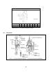
Figure 2-2 Hoist Part Identification Diagrams – 25 Ton TCR25000P2 and TCR25000C2 11
3.0 Preoperational Procedures 3.1 Air Supply System Requirements 3.1.1 3.1.2 3.1.3 3.2 NOTICE Pressure and Flow - Verify that the air supply system has capacity to supply your air hoist with required pressure and flow. Otherwise the hoist may operate poorly or may fail to operate. See Section 3.2. CAUTION Lubrication - The hoist requires lubrication for proper operation. The oil in the air supply is the primary source of lubrication to the hoist.
3.4.2 The filter servicing the hoist can also service other hoists and air consuming equipment. In this case, the air filter must be in sized for the total air consumption of the equipment it is servicing. Air Dryer - CAUTION 3.5 To prevent corrosion and hoist malfunction, employ an air dryer in the air supply system to ensure that dry air is supplied to the hoist.
3.6.2 NOTICE Piping - Pipe should be sized to accommodate the hoist airflow requirements. Table 3-1 gives recommended pipe sizes. Table 3-1 Air Supply Pipe and Hose Sizes 3.6.3 Model Diameter of Supply Pipe Diameter of Supply Hose TCR10000P2 TCR25000C2 TCR10000P2 TCR25000C2 Inside diameter 1.25 inch or larger Inside diameter 1.0 inch or larger NOTICE Hoses - The connection from the air supply system piping to the hoist must be made with a flexible pressure hose.
3.6.5 3.7 Mounting Location 3.7.1 3.7.2 3.8 CAUTION Before connecting the hoist to its air supply line; perform the proper draining and purging procedures to prevent contaminants or moisture from entering the hoist. WARNING Prior to mounting the hoist ensure that the suspension and it supporting structure are adequate to support the hoist and its loads. If necessary consult a professional that is qualified to evaluate the adequacy of the suspension location and its supporting structure.
3.10 Non-Stationary Application 3.10.1 For applications such as rental fleets or construction sites where the hoist is moved from place-toplace, a filter and lubricator are still required. Consult factory for recommended methods. 3.10.2 Connections and fittings must be kept clean and care taken to prevent dirt, debris and moisture from entering the hoist. 3.10.
Figure 3-6 Capsized Hook and Chain 3.11.3 WARNING Confirm the adequacy of the rated capacity for all slings, chains, wire ropes and all other lifting attachments before use. Inspect all load suspension members for damage prior to use and replace or repair all damaged parts. 3.11.4 WARNING Verify that the Chain/Limit Levers are operational and can move freely in both the up and down directions. For reference see Figure 3-7.
Figure 3-8 Limit Switch Components – 25 Ton TCR25000C2 and TCR25000P2 3.11.5 Measure and record the “K” dimension of all hooks on hoist. See Table 5-6 under Section 5, “Inspection”. Always use the same side of the hook to measure and record the "K" dimension. 3.11.6 Record the hoist Code Number and Serial Number (from the nameplate on the hoist – see Section 10) in the space provided on the cover of this manual. 3.11.
4.0 Operation 4.1 Introduction DANGER DO NOT WALK UNDER A SUSPENDED LOAD WARNING HOIST OPERATORS SHALL BE REQUIRED TO READ THE OPERATION SECTION OF THIS MANUAL, THE WARNINGS CONTAINED IN THIS MANUAL, INSTRUCTION AND WARNING LABELS ON THE HOIST OR LIFTING SYSTEM, AND THE OPERATION SECTIONS OF ANSI/ASME B30.16 and ANSI/ASME B30.10. THE OPERATOR SHALL ALSO BE REQUIRED TO BE FAMILIAR WITH THE HOIST AND HOIST CONTROLS BEFORE BEING AUTHORIZED TO OPERATE THE HOIST OR LIFTING SYSTEM.
The operation of an overhead hoist involves more than activating the hoist’s controls. Per the ANSI/ASME B30 standards, the use of an overhead hoist is subject to certain hazards that cannot be mitigated by engineered features, but only by the exercise of intelligence, care, common sense, and experience in anticipating the effects and results of activating the hoist’s controls.
CAUTION Improper operation of a hoist can create a potentially hazardous situation which, if not avoided, could result in minor or moderate injury, or property damage. To avoid such a potentially hazardous situation THE OPERATOR SHALL: • Maintain a firm footing or be otherwise secured when operating the hoist. • Use the hoist manufacturer’s recommended parts when repairing the unit. • Check brake function by tensioning the hoist prior to each lift operation.
4.3.3 Cord Control - When using a hoist with cord control, pull down on the appropriate colored cord to raise or lower the hoist. White indicates the raise control and red indicates lowering control. Release the cords to stop the hoist. Refer to Figure 4-2 below. Figure 4-2 Cord Control 4.3.4 4.4 CAUTION Make sure the motor completely stops before reversing direction. Adjusting the Controls 4.4.1 For pendant control, the speed can be adjusted by the amount the lever is depressed.
4.5 Operation of the Load Limiter 4.5.1 If a hoist is used to lift a load that exceeds the hoists rated capacity, the load limiter will cause the hoist to automatically stop lifting. 4.5.2 If the hoist stops lifting automatically, lower and remove the load from the hoist. 4.5.3 If the load is at or below the hoist’s capacity rating and the hoist stops lifting automatically, the load limiter may need adjustment. Check air line pressure to ensure adequate pressure at the hoist.
5.0 Inspection 5.1 General 5.1.1 The inspection procedure herein is based on ANSI/ASME B30.16. The following definitions are from ANSI/ASME B30.16 and pertain to the inspection procedure below. Designated Person - a person selected or assigned as being competent to perform the specific duties to which he/she is assigned.
5.3 Frequent Inspection 5.3.1 Inspections should be made on a FREQUENT basis in accordance with Table 5-1, “Frequent Inspection.” Included in these FREQUENT Inspections are observations made during operation for any defects or damage that might appear between Periodic Inspections. Evaluation and resolution of the results of FREQUENT Inspections shall be made by a designated person such that the hoist is maintained in safe working condition.
5.5 Occasionally Used Hoists 5.5.1 Hoists that are used infrequently shall be inspected as follows prior to placing in service: Hoist Idle More Than 1 Month, Less Than 1 Year: Inspect per FREQUENT Inspection criteria of Section 5.3 above. Hoist Idle More Than 1 Year: Inspect per PERIODIC Inspection criteria of Section 5.4 above. 5.6 5.7 Inspection Records 5.6.
Table 5-3 Hoist Inspection Methods and Criteria (continued) Item Method Criteria Action Hooks - Bent Shank or Neck Visual Shank and neck portions of hook should be free of deformations Replace. Hooks - Yoke Assembly Visual Should be free of significant rust, weld splatter, nicks, gouges. Holes should not be elongated, fasteners should not be loose, and there should be no gap between mating parts. Clean/Lubricate, or replace as required.
Table 5-3 Hoist Inspection Methods and Criteria (continued) Item Method Criteria Action Housing and Mechanical Components Visual, Auditory, Vibration, Function Hoist components including load blocks, suspension housing, chain attachments, clevises, yokes, suspension bolts, shafts, gears, bearings, pins and rollers should be free of cracks, distortion, significant wear and corrosion. Evidence of same can be detected visually or via detection of unusual sounds or vibration during operation.
Table 5-4 Brake Disc Dimension Hoists Parts View Figure No. TCR10000C2 TCR10000P2 TCR25000C2 TCR25000P2 Std Dimension Inch (mm) Minimum Value for Replacement Inch (mm) T = 0.16 (4.0) T = 0.10 (2.5) Table 5-5 Chain Guide/Side Plate Dimensions Hoists Parts View Figure No. TCR10000C2 TCR10000P2 146 TCR25000C2 TCR25000P2 161 & 162 Std Dimension Maximum Value for Replacement Inch (mm) Inch (mm) L = 1.57 (40) L = 1.69 (42.8) W = 2.36 (60) W = 2.48 (63) L = 2.20 (55.8) L = 2.36 (60) W = 3.
Table 5-6 Top Hook & Bottom Hook Dimensions Dimensions K and U should be measured and recorded below prior to any use when the hook is first placed into service. Hoists TCR10000C2 TCR10000P2 TCR25000C2 TCR25000P2 Parts View Figure No. Recorded Dimension When New Maximum/Minimum Value for Replacement 165 Top Hook K = _______________ Top Hook U = _______________ Bottom Hook K = ____________ Bottom Hook U = ____________ For K if the measured dimension exceeds 1.
6.0 Lubrication 6.1 Air Hoist Lubrication 6.1.1 6.1.2 6.1.3 6.2 6.3 See Section 3.0 for lubrication requirements. CAUTION Lubrication to the motor will be provided primarily by the air supply lubricator. The recommended amount is 10-15 drops/minute (2-3cc/min.). Refer to Table 6-1 below for the approved lubricant for use with your air hoist. Additional lubrication to the reduction gears is not necessary.
7.0 Maintenance and Handling 7.1 Load Limiter 7.1.1 The purpose of the load limiter is to prevent using the hoist in an overload situation. When lifting, the hoist will stop automatically if the load is above the rated capacity of the hoist. 7.1.2 The adjustment is factory set to actuate at approximately125% of rated capacity (based on supply air pressure of 90 PSI). Note: the load limiter may need adjustment to compensate for air supply pressures significantly less than 90 PSI.
4) Put a load equal to the desired actuation point on the hoist's hook (do not exceed 125% of the hoist's rated capacity). Begin to slowly lift the load, then increase the lifting speed. Return the load to its resting position so the load chain is not under tension. 5) If the load limiter prevents lifting, turn the adjustment screw IN one full turn. 6) Repeat steps 4 and 5 until the load limiter allows lifting. 7) Turn the adjustment screw OUT ¾ of a turn.
Figure 7-2 Brake Inspection Diagram 7.3 Load Chain 7.3.1 Lubrication and Cleaning Clean the chain with an acid-free cleaning solution. The load chain should be kept clean and lubricated. Lubrication - Clean and lubricate the load chain per Section 6 at least once every 3 months for normal usage. Clean and lubricate more frequently for heavier usage or severe conditions. 7.3.2 Replacement 1) 2) 3) CAUTION An air supply line must be connected to the hoist in order to perform the following procedures.
7) While pulling on the wire, SLOWLY operate hoist in the DOWN direction to thread the load chain over the load sheave. Make sure the chain feeds smoothly while operating the hoist. If binding occurs, stop and SLOWLY operate the hoist in the up direction to the back the chain out, then reorient the load sheave as instructed in step 5 before attempting to reinsert the load chain. 8) Operated the hoist in the down direction until sufficient there is sufficient load chain to reeve the hoist.
7.4 Pendant 7.4.1 The following procedure covers the installation of a pendant control station. 1) Attach the strain relief chain and the three hoses to the pendant station. 2) Attach the strain relief chain to the hoist valve body with the socket bolt as shown in Figure 7-4. 3) Attach the three hoists to the fittings on the hoist's valve body. Refer to Figure 7-4 and make sure the up, down and supply hoses are attached to the correct locations.
7.5 7.6 Storage 7.5.1 Whenever the hoist is to be placed into storage, place extra lubricating oil into the air inlet opening and circulate the air motor before plugging the inlet. Make certain that no debris, dirt or moisture is allowed to enter the air hoist through air inlet opening during preparations for storage. 7.5.2 The storage location should be clean and dry. Outdoor Installation 7.6.1 For hoist installations that are outdoors, the hoist should be covered when not in use. 7.6.
8.0 Troubleshooting WARNING HAZARDOUS AIR PRESSURE IS PRESENT IN THE HOIST, IN THE SUPPLY OF COMPRESSED AIR TO THE HOIST, AND IN CONNECTIONS BETWEEN COMPONENTS. Before performing ANY maintenance on the equipment, de-energize the supply of compressed air to the equipment, and lock and tag the supply device in the de-energized position. Refer to ANSI Z244.1, “Personnel Protection - Lockout/Tagout of Energy Sources.” Only Trained and competent personnel should inspect and repair this equipment.
Table 8-1 Troubleshooting Guide (continued) Symptom Hoist moving in wrong direction (pendant control) Hoist lowers but will not lift Hoist continues running after pendant or cord is released Hoist drifts excessively when hoist is stopped Cause Remedy Pendant control hoses are terminated to incorrect ports on hoist body. Hoist is overloaded. Faulty pendant control or control hose(s) Lack of air pressure or partial loss of or leakage in air supply. Connect the control tubes in accordance with Section 7.
9.0 Warranty Warranty explanation and terms. All products sold by Harrington Hoists, Inc.
10.0 Parts Information A complete parts list is available from Harrington Hoists and is supplied separately with your hoist. The parts list is also available from Harrington's web site (www.harringtonhoists.com) or from any Harrington facility (see back cover of this manual). When ordering Parts, please provide the Hoist code number located on the Hoist nameplate (see fig. below). Reminder: Per Sections 3.11.6 and 1.
NOTES 42
NOTES 43
www.harringtonhoists.com Harrington Hoists, Inc. 401 West End Avenue Manheim, PA 17545-1703 Phone: 717-665-2000 Toll Free: 800-233-3010 Fax: 717-665-2861 Harrington Hoists – Western Division 2341 Pomona Rincon Rd.