EFFECTIVE: February 3, 2011 MANUAL CHAIN HOIST CB SERIES MODEL M3 1/2 Ton through 20 Ton Capacity Code, Lot and Serial Number This equipment should not be installed, operated or maintained by any person who has not read and understood all the contents of this manual. Failure to read and comply with the contents of this manual can result in serious bodily injury or death, and/or property damage.
Table of Contents Section 1.0 2.0 3.0 4.0 5.0 Page Number Important Information and Warnings ……………………………………………………………………… 4 1.1 Terms and Summary 1.2 Warning Tags and Labels Technical Information…………………………………………………………………………….…………. 7 2.1 Specifications 2.2 Dimensions 2.3 Optional Equipment Preoperational Procedures ……………………………………………………………………………… 11 3.1 Chain 3.2 Attachment Points 3.3 Mounting the Hoist 3.
Section 6.0 Page Number Maintenance & Handling …………………………………………………………………………………. 26 6.1 Lubrication 6.2 Disassembly, Assembly and Adjustment 6.3 Hoist Disassembly 6.4 Hoist Assembly 6.5 Storage 6.6 Outdoor Installation 7.0 Troubleshooting …………………………………………………………………………………………… 36 8.0 Warranty …………………………………………………………………………………………………… 39 9.
1.0 Important Information and Warnings 1.1 Terms and Summary This manual provides important information for personnel involved with the installation, operation and maintenance of this product. Although you may be familiar with this or similar equipment, it is strongly recommended that you read this manual before installing, operating, or maintaining the product. Danger, Warning, Caution, and Notice Throughout this manual there are steps and procedures that can present hazardous situations.
Equipment described herein is not designed for and MUST NOT be used for lifting, supporting, or transporting people, or for lifting or supporting loads over people. Equipment described herein should not be used in conjunction with other equipment unless necessary and/or required safety devices applicable to the system, crane, or application are installed by the system designer, system manufacturer, crane manufacturer, installer, or user.
1.2 Warning Tags and Labels The warning tag illustrated below in Figure 1-1 is supplied with each hoist shipped from the factory. If the tag is not attached to your hoist’s no-load side of the load chain, order a tag from your dealer and install it. Read and obey all warnings attached to this hoist. Tag is not shown actual size.
2.0 Technical Information 2.1 Specifications 2.1.1 Product Code 2.1.2 Operating Conditions and Environment Temperature range: Humidity: Cap. (Tons) Product Code ½ 1 1½ 2 2½ 3 5 8 10 15 20 CB005 CB010 CB015 CB020 CB025 CB030 CB050 CB080 CB100 CB150 CB200 Std.
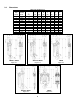
2.2 Dimensions Cap. (Tons) Product Code 1/2 1 1 1/2 2 2 1/2 3 5 8 10 15 20 CB005 CB010 CB015 CB020 CB025 CB030 CB050 CB080 CB100 CB150 CB200 Table 2-2 Hoist Dimensions Headroom a b d c (in) (in) (ft) (in) 11.2 11.6 13.8 14.8 16.5 20.1 23.6 30.3 29.9 40.2 46.5 CB005 to CB025 Figure 2-1 6.2 6.4 6.7 7.2 7.6 6.7 7.6 7.6 7.6 10.6 14.7 6.3 6.3 7.2 8.0 9.2 9.3 11.1 14.7 17.2 19.4 29.4 8.0 8.0 8.0 8.0 8.0 8.3 10.0 10.3 14.9 15.9 16.3 e (in) f (in) g (in) x (in) 2.7 2.8 3.1 3.4 3.6 3.1 3.6 3.6 4.4 4.
Table 2-3 Hook Dimension* T = Top Hook B = Bottom Hook Units = inch Cap. (Tons) Product Code 1/2 Hook a b c d e g CB005 0.8 0.5 0.7 0.5 1.4 1.1 1 CB010 1.0 0.6 0.9 0.6 1.7 1.1 1½ CB015 1.2 0.8 1.0 0.8 1.9 1.3 2 CB020 1.4 0.9 1.2 0.9 2.0 1.4 2½ CB025 3 CB030 1.6 1.0 1.3 1.0 2.1 1.6 1.8 1.1 1.5 1.1 2.2 1.7 5 8 CB050 2.2 1.4 1.9 1.4 2.5 1.8 CB080 3.0 1.9 2.5 1.9 3.3 2.9 10 CB100 3.0 1.9 2.5 1.9 3.3 2.9 15 CB150 3.7 2.4 3.
2.3.2 Optional Inspection Hooks The Inspection Hook is designed to facilitate the inspection of the internal surfaces of the hook yoke and shank portion of the hook itself. The Inspection Hook is suitable for applications where inspection of the internal parts of the hook set is required. The inspection hook uses the standard Harrington hook set and is assembled with high-strength locking fasteners instead of rivets. Inspection hooks are available in top and bottom versions. Refer to Figure 2-7.
3.0 Preoperational Procedures 3.1 Chain 3.1.1 Verify that the load chain is not twisted or tangled prior to operating the hoist. Make sure the bottom hook on the 3 (CB030) through the 20 (CB200) Ton multiple fall hoists is not capsized. See Figures 3-1 and 3-2. Correct all chain irregularities before conducting the first hoist operation.
3.2 Attachment Points 3.2.1 Prior to attaching the hoist ensure that all attachment points, suspension components and supporting structure are adequate to support the hoist and its load. If necessary consult a professional that is qualified to evaluate the adequacy of the suspension location and its supporting structure. 3.2.2 3.3 Mounting the Hoist 3.3.1 3.3.2 3.4 See Section 6.6 for outdoor installation considerations.
4.0 Operation 4.1 Introduction DO NOT WALK UNDER A SUSPENDED LOAD HOIST OPERATORS SHALL BE REQUIRED TO READ THE OPERATION SECTION OF THIS MANUAL, THE WARNINGS CONTAINED IN THIS MANUAL, INSTRUCTION AND WARNING LABELS ON THE HOIST OR LIFTING SYSTEM, AND THE OPERATION SECTIONS OF ANSI/ASME B30.16 and ANSI/ASME B30.10. THE OPERATOR SHALL ALSO BE REQUIRED TO BE FAMILIAR WITH THE HOIST AND HOIST CONTROLS BEFORE BEING AUTHORIZED TO OPERATE THE HOIST OR LIFTING SYSTEM.
4.2 Shall’s and Shall Not’s for Operation Improper operation of a hoist can create a potentially hazardous situation which, if not avoided, could result in death or serious injury, and substantial property damage. To avoid such a potentially hazardous situation THE OPERATOR SHALL: • NOT lift more than rated load for the hoist. • • NOT use damaged hoist or hoist that is not working properly. NOT leave load supported by the hoist unattended unless specific precautions have been taken.
Improper operation of a hoist can create a potentially hazardous situation which, if not avoided, could result in minor or moderate injury, or property damage. To avoid such a potentially hazardous situation THE OPERATOR SHALL: worn parts, and keep appropriate records of maintenance. • Maintain a firm footing or be otherwise secured when operating the hoist. • Check brake function by tensioning the hoist prior to each lift operation.
5.0 Inspection 5.1 General 5.1.1 5.2 The inspection procedure herein is based on ANSI/ASME B30.16. The following definitions are from ANSI/ASME B30.16 and pertain to the inspection procedure below. Designated Person – a person selected or assigned as being competent to perform the specific duties to which he/she is assigned.
5.3 Frequent Inspection 5.3.1 Inspections should be made on a FREQUENT basis in accordance with Table 5-1, “Frequent Inspection.” Included in these FREQUENT Inspections are observations made during operation for any defects or damage that might appear between Periodic Inspections. Evaluation and resolution of the results of FREQUENT Inspections shall be made by a designated person such that the hoist is maintained in safe working condition.
5.5 Occasionally Used Hoists 5.5.1 5.6 5.7 Hoists that are used infrequently shall be inspected as follows prior to placing in service: Hoist Idle More Than 1 Month, Less Than 1 Year: Inspect per FREQUENT Inspection criteria in Section 5.3. Hoist Idle More Than 1 Year: Inspect per PERIODIC Inspection criteria in Section 5.4. Inspection Records 5.6.
Table 5-3 Hoist Inspection Methods and Criteria Item Method Discard Limit/Criteria Action Hooks – Yoke Assembly Visual Should be free of significant rust, weld splatter, nicks, and gouges. Holes should not be elongated, fasteners should not be loose, and there should be no gap between mating parts. Tighten or replace as required. Hooks – Idle Sheave and Shaft (Multiple Fall Hoist) Visual, Function Pockets of Idle Sheave should be free of significant wear.
Table 5-3 Hoist Inspection Methods and Criteria Item Method Discard Limit/Criteria Action Braking System – Components Visual Brake Pawl, Pawl Pin, and Pawl Spring should not be deformed, scarred, or show significant wear. Refer to Figure 5-2 (34 & 33). Replace. Brake – Damage to Brake Surface Visual Damage due to scratching or gouging by foreign matter. Refer to Figure 5-2 (37, 38, & 40). Replace.
Twisted Hook Hook Swivel Figure 5-1 Top & Bottom Hook Checks Table 5-4 Top Hook & Bottom Hook Dimensions “k” Measured When New: Top: _________________________ Bottom: ______________________ Product Code Nominal "k" Dimension* inch (mm) CB005 CB010 CB015 CB020 CB025 CB030 CB050 CB080 CB100 CB150 CB200 1.76 (44.6) 1.92 (48.8) 2.22 (56.3) 2.36 (59.9) 2.52 (64.1) 2.72 (69.1) 3.06 (77.8) 4.56 (115.9) 4.56 (115.9) 5.52 (140.2) 5.62 (142.8) "u" Dimension inch (mm) Standard Discard 0.67 (17.0) 0.60 (15.3) 0.
Table 5-5 Chain Pin Hole and Top Pin Hole Wear Dimensions Hole Diameter (d) Product Code CB005 CB010 CB015 CB020 CB025 CB030 CB050, CB080, CB100 CB150 CB200 Chain Pin Hole inch (mm) Top Pin Hole inch (mm) Standard 0.252 (6.4) 0.319 (8.1) 0.350 (8.9) 0.394 (10.0) 0.445 (11.3) 0.350 (8.9) Discard 0.272 (6.9) 0.339 (8.6) 0.370 (9.4) 0.413 (10.5) 0.465 (11.8) 0.370 (9.4) Standard 0.480 (12.2) 0.480 (12.2) 0.638 (16.2) 0.638 (16.2) 0.638 (16.2) 0.646 (16.4) Discard 0.500 (12.7) 0.500 (12.7) 0.658 (16.
Table 5-8 Chain Wear Dimensions Product Code CB005 CB010 CB015, CB030 CB020 CB025, CB050, CB080, CB100, CB150, CB200 “P” Dimension inch (mm) Standard Discard 2.97 (75.5) 3.06 (77.7) 3.76 (95.5) 3.87 (98.3) 4.17 (106.0) 4.30 (109.1) 4.76 (121.0) 4.91 (124.6) “d” Dimension inch (mm) Standard Discard 0.20 (5.0) 0.18 (4.5) 0.25 (6.3) 0.22 (5.7) 0.28 (7.1) 0.25 (6.4) 0.32 (8.0) 0.28 (7.2) 5.35 (136.0) 0.35 (9.0) 5.51 (140.0) Figure 5-2 Brake Assembly 23 0.32 (8.
Table 5-9 Friction Plate Wear Dimensions Thickness inch (mm) Product Code All Standard Discard 0.118 (3.0) 0.098 (2.5) Table 5-10 Brake Bushing Wear Dimensions A Dimension Product Code CB005, CB010, CB015, CB030 CB020, CB025, CB050, CB080, CB100, CB150, CB200 inch (mm) Standard Discard 0.118 (3.0) 0.079 (2.0) 0.157 (4.0) 0.118 (3.0) Table 5-11 Brake Ratchet Disc Wear Dimensions D Dimension Product Code inch (mm) Standard Discard CB005, CB010, CB015, CB030 2.71 (69) 2.60 (66) CB020 3.
Figure 5-3 Pocket Wheel Figure 5-4 Load Gear Assembly Figure 5-5 Top Hook Assembly 25
6.0 Maintenance and Handling 6.1 Lubrication 6.1.1 Load Chain For longer life, the load chain should be lubricated. The load chain lubrication should be accomplished after cleaning the load chain with an acid free cleaning solution. Apply Harrington lubricating grease (Part No. ER1BS1951) or an equivalent to industrial general lithium grease, NLGI No. 0, to the bearing surfaces of the load chain links as indicated by the shaded areas in Figure 6-1.
6.2 Disassembly, Assembly and Adjustment 6.2.1 1) Perform proper disassembly or assembly in accordance with this manual. 2) The hoist utilizes dry friction plates; they are not to be lubricated. 3) Do not extend the load chain. 4) Remove old grease on the disassembled parts. 5) Replace components with Harrington Hoist approved parts. 6) To reassemble, apply new grease, and use a new split pin and snap ring. 6.2.2 Tools – The following tools are required to disassemble/reassemble the hoist. No.
9) For 8 ton capacity and under: Pull the split pin [24] out from the stopper pin [23] and remove the load chain [47] and the stopper pin from the stopper [22]. 10) For 10 ton capacity and above: Pull the split pin [52] out from the end pin [51] and remove the load chain [47] and the end pin. Unscrew two socket bolts (with the spring washers) fixing the stoppers [114] and remove the stoppers. 11) Remove the load chain [47] from the load sheave [14] by pulling the load chain toward the bottom hook.
Figure 6-1 Load Sheave/Pinion Assembly 2) Grease the balls of the ball bearing [15]. Orient side plate A [11] with brake cover side down and insert the ball bearing [15] (with a snap ring side up) into the side A. 3) Insert the load sheave [14] with a part of spline side (pinion gear side) up into the ball bearing [15]. The stripper [21] must be inserted as well. See Figure 6-2.
Figure 6-3 Side Plate Assembly 6) Join the side plate B [13] to the side plate A [11]. *NOTE: In case it is difficult to join the two, tap it with a rubber mallet. Be careful not to let the stripper, guide roller or stopper fall down. 7) Mesh the load gear [25] with the splines of the load sheave [14] and fix it with a snap ring [26]. : Always make sure the snap ring is completely seated at the bottom of the groove.
11) Place the top hook [1] between side plates A [11] and B [13]. Then insert top pin [4] and fix it with the split pin [5]. : Always bend the split pin securely after inserting it into the top pin. Figure 6-5 Gear Train Assembly 12) Place the hand wheel [40] side upward. 13) Reeve the load chain [47] turning the pinion clockwise through the space between the left (bottom hook side) guide roller [20] and the load sheave [14]. See figure 6-6.
Figure 6-6 Reeving Assembly 14) For 8 ton capacity and below: Pull the end of the load chain [47] out between the right guide roller [20] and the load sheave [14] (no load side) and insert it to the anchorage (stopper) [22]. Insert the stopper pin [23] and fix it with a split pin [24]. : Make sure the load chain is not twisted and the split pin in the stopper pin is bent securely.
For 10 ton capacity and above: Connect the no load end of the load chain [47] to the end pin [51] which is to be inserted from gear case [29] side. Use a split pin [52] to secure the end pin. Assemble stoppers [114] to the ninth link from the no load end of the load chain by socket bolts and spring washers. *NOTE: Threaded hole of one stopper shall face to non-threaded hole of the other stopper. Socket bolt shall be inserted from the non-threaded side.
Figure 6-9 Pawl & Brake Assembly 18) Wipe out any dirt on the brake surface of the hand wheel [40] and apply machine oil to the threaded part of it. Screw it on the pinion [17] shaft all the way down. 19) Place the wheel stopper [41] on the head of the pinion [17], insert the wheel stopper pin [42] and fix it with a split pin [43]. : Never forget to bend the split pin after inserting into the wheel stopper pin. 20) Put the hand chain [48] around the hand wheel [40]. See figure 6-10.
21) Assemble the wheel cover [44] to the side plate A [11] and fix them with the spring washer [46] and the nut [45]. 22) Insert the other end of the load chain [47] to the bottom hook [6] and fix them with the chain pin [8], slotted nut [9] and split pin [10]. See figure 6-11. : Always bend the split pin securely. Figure 6-11 Bottom Hook Assembly 6.5 Storage 6.5.1 : IMPROPER chain hoist use could result in death or serious injury. To avoid these hazards: 6.
7.0 Troubleshooting Read and comply with instructions in this manual and use the hoist properly. Checking the sounds from the hoist in operation is a critical inspection. Note hoist sounds during operation. If a defect is found in the hoist, stop using it immediately and check the cause of the defect. Only Trained and competent personnel should inspect and repair the hoist.
Symptom Cause Remedy Hoist will lift intermittently – Poor pawl movement caused by faulty pawl spring. The spring is loose or damaged. Perform maintenance and/or repair. Slight or irregular clicking Mis-assembly of pawl spring Reassemble it properly and ensure to check click sound of the pawl before reuse. Reassemble properly and ensure proper lifting before reuse. During operation, hoist idles or load drifts Poor contact of load sheave and load chain caused by improper chain-reeving.
Table 7-1 Troubleshooting Guide Improper braking may cause improper load lowering. The hoist utilizes dry friction discs; do not apply oil to friction surfaces. Symptom Cause Remedy Over tightened brake The hoist left under load for a long period Load will not go down Pull down hard (possibly with 2 people) on the hand chain to loosen brake. Shock loaded during operation Brake rusted tight Replace the rusty components and perform hoist maintenance.
8.0 Warranty All products sold by Harrington Hoists, Inc.
This Page Intentionally Left Blank 40
9.0 Parts List When ordering Parts, please provide the Hoist model number, lot number, and serial number located on the Hoist nameplate (see Figure 9-1 below). Reminder: Per Sections 1.1 and 3.4.4 to aid in ordering parts and product support, record the hoist Code, Lot and Serial Number in the space provided on the cover of this manual. Figure 9-1 - M3CB Nameplate The parts list is arranged into the following sections: Section Page 9.1 1/2 to 20 Ton Parts………………….…………………………………………………...……….……...42 9.
9.
9.1 1/2 to 20 Ton Parts Fig. No.
9.1 1/2 to 20 Ton Parts Fig. No.
This Page Intentionally Left Blank 45
9.
9.2 3 to 20 Ton Parts Fig. No. Part Name 51 52 53 End Pin Split Pin Cross Guide 54 Top Hook Set 55 56 57 58 59A 59B Top Hook Top Hook Ass’y Latch Assembly Idle Sheave Ass’y Shaft Assembly Top Yoke A Top Yoke B 60 Socket Bolt 61 Lever Nut 62 63 Socket Bolt U-Nut Top Susp.
9.2 3 to 20 Ton Parts Fig. No.
9.2 3 to 20 Ton Parts Fig. No. 106 107 108 Part Name 110 Chain Pin Slotted Nut Split Pin Nameplate B w/ Rivets Nameplate B w/ Rivets (M3B Model) Load Chain 111 Hand Chain 109 112 Warning Tag 113 Chain Stopper Link 114 Stopper Assembly Capacity (T) Qty per Hoist 3 1 1 1 M3041030 M2049010 9009411 1 M3800030 1 5 8 10 15 M3041075 M2049020 9009412 M3800080 M3800050 M3800030 M3B800100 M3B800150 2 1@ ft. 1@ ft. 2@ ft.
9.3 CB Slip Clutch Device 50 Figure 9-4 Slip Clutch FIG NO. 1 PART NAME OLL ASSEMBLY 2 PINION 3 HAND WHEEL 4 WASHER 5 NUT (left hand thread) 6 Split Pin QTY M3 M3B M3 M3B M3 M3B M3 M3B M3 M3B M3 M3B 1 1 1 CAPACITY 1/2 T 1T 1 1/2 & 3 T 2T 2 1/2-5 T M3CB005OD M3CB010OD M3CB015OD M3CB020OD M3CB025OD 8-10-15-20 T* M3B025OD C3YA111005 C3YA111010 C3YA111015 C3YA111020 C3YA111025 C3BYA111025 C3YA1115005 1 1 1 *20 Ton capacity requires Quantities of 2.
9.4 Optional Hooks Figure 9-5 Bullard®, Shur-Loc® and Inspection Hooks Bullard® Hooks Fig. No.
9.4 Optional Hooks Shur-Loc® Hooks Parts Per Hoist ½T 1T 1½T 2T 2½T 1 6030201 6030202 6030203 6030204 6030205 Shur-Loc Hook Assembly 1 60140 60142 60144 60145 60146 3 Top Yoke Kit 1 TYKITCB005 TYKITCB010 TYKITCB015 TYKITCB020 TYKITCB025 4 Button Head Screw 2 9012601 5 Flexloc Nut 2 9012603 6 Warning Tag 1 Fig. No.
9.5 Optional Chain Containers Figure 9-6 M3CB Optional Chain Container CF4 OPTIONAL CHAIN CONTAINERS Fig. No.
NOTES 54
NOTES 55
www.harringtonhoists.com Harrington Hoists, Inc. 401 West End Avenue Manheim, PA 17545-1703 Phone: 717-665-2000 Toll Free: 800-233-3010 Fax: 717-665-2861 Harrington Hoists – Western Division 2341 Pomona Rd.