
Owner's manual

P/N HS-5010 REV. C
page 7 of 12
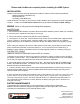
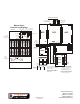
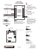
All wiring with exception of
120 VAC and Battery Connection
is Power-Limited.
Route AC power and Battery
wires to bottom-left or lower-left
side K.O.
*1
All Power Limited wiring must
maintain a min. 1/4“ separation
from Non Power Limited wiring.
(This requirement may be waived if
Type FPL, FPLR or FPLP wire is used
for Power Limited circuits)
TB1 TB2
TB3 TB4 TB5P1
P2
P3
P4
J1
1
2
3
LED3LED2LED1
NetCom Bus
(Supervised)
*A *A
*A - Optional wiring for
Style 7 supervision
+
-
+
-
120 VAC
(Supervised)
*1
24V Battery
(Supervised)
*1
FF
II
RR
EE
E
O
L
EOLR
FF
II
RR
EE
FF
II
RR
EE
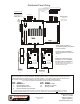
Standard Life Safety Speakers, Strobes connected and powered separately
Break wire to maintain supervision. Do not loop wire around speaker terminals
CLASS “B” (Style “Y”)
WIRING
Supervised - Power Limited
Fire
Phone
Loop
FF
II
RR
EE
FF
II
RR
EE
EOL
CLASS “A” (Style “Z”)
WIRING
Supervised
Power Limited
Matching
EOLR
MBR
TB2
TB3
TB4
TB10
J5
J6
J7
TB9
TB5
TB6
TB7
TB8
TB11
1 2 3 4
TB1
1 2 3 4
1 2 3 4
1 2 3 4
1 2 3 4
1 2 3 4
1 2 3 4
J8
J11
J9
J1
J2
J3
J4
LED1
P9
P10
P11
P12
P13
P14
P15
P16
P1 P2 P3 P4 P5 P6 P7 P8
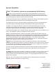
31
Supervised
Power Limited
1
2
3
4
25 or 50W max depending
on amplifier used.
Speaker line EOLR must be
equal to Matching EOLR
installed on TB9. All must be
Listed EOL devices.
SPEAKER OUTPUT
EVX-25E
EVX-50E
EVX-100E
TB1
1 2 3
4
5 6 7 8
TB3
1
2
3
4
5
6
7
8
MESSAGE
GAIN
MIC
GAIN
FAULT
NORMAL
ALARM
YEL
GRN
RED
TB2
1
2
3
4
5
6
7
8
9
10
11
P2
S1
SN1
1 2 3
J2
J1
1
2
EVX-25E
EVX-50E
EVX-100E
TB1
1 2 3
4
5 6 7 8
TB3
1
2
3
4
5
6
7
8
MESSAGE
GAIN
MIC
GAIN
FAULT
NORMAL
ALARM
YEL
GRN
RED
TB2
1
2
3
4
5
6
7
8
9
10
11
P2
S1
SN1
1 2 3
J2
J1
1
2
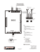
Distributed Panel Wiring
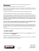
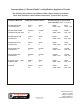
EVX 25(E) / 50(E) / 100(E) TROUBLE CODES
When a unit goes into a Trouble Condition, the Yellow LED wil remain on until the trouble is cleared. The Green
LED will flash a Code to indicate the type of Trouble Condition. There will be a pause between repeats of the
code. When multiple Trouble Conditions occur at the same time, the codes will add together.
The number of flashes and associated Trouble Condition are listed below.
Code Trouble Code Trouble
1 Power Failure 8 Amplifier Trouble
2 Open Speaker Circuit 16 Microphone Trouble
4 Shorted Speaker Circuit 32 Battery Trouble
6 External Trouble / Ground Fault
* 6 flashes typically indicates “External Trouble”, such as an EVX-RM. If LED 4 is on, the 6 flash indicates a ground fault.
If both a ground fault condition and an external trouble occur simultaneously, the fault codes will not combine for 12 flash.
2519 Fourth Avenue
Moline, IL 61265
(800) 577-5758 (v)
(309) 762-8215 (f)
www.harringtonfire.com