
Owner's manual
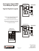

P/N HS-5010 REV. C
page 8 of 12
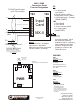
TB1 TB2
TB3 TB4 TB5P1
P2
P3
P4
J1
1
2
3
LED3LED2LED1
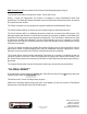
DCC
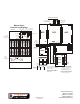
Master Panel DCC
Connection Detail
Terminal Designation
1 - Earth (Chassis)
2 - Circuit NEG
3 - + 24 VDC @
160 mA (Remote)
220 mA (Master)
4 - Fault (Pull Down 0V)
Primary data loop
1 - Rx - (From last/previous DCC)
2 - Rx +
Secondary data loop
3 - Rx - (From last/previous DCC)
4 - Rx +
TB3
TB1
Primary data loop
1 - Tx - (To first/next DCC)
2 - Tx +
Secondary data loop
3 - Tx - (To first/next DCC)
4 - Tx +
TB2
TB4 Not Connected
TB5 Not Connected
3
TB2
PWR
(Factory wired)
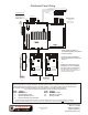
3 2 1
1 2 4
Twisted Pair
Optional - Style 7
Supervision
Conduit
Each Send/Return
Loop must be run
in it’s own conduit
Style 4
Supervision
*J1 Removed
*
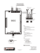
*J1 - Pos 1-2 for Master Panel
Pos 2-3 for Dist. Panel
Dist. Panel
DCC
TB3
EVX-25E/50E/100E
TB2
2------------------1
3-----------------10
(Factory wired)
J1
1
2
3
J1
1
2
3
Master
Dist.
TB1 TB2
From
Last
To
Next
Supervised - Power Limited
Supervised
Power Limited
(MP-DCC wiring shown)
2519 Fourth Avenue
Moline, IL 61265
(800) 577-5758 (v)
(309) 762-8215 (f)
www.harringtonfire.com