
User Manual


- 1 -
Commercial Products Group
2519-4th Ave, Moline, IL61265
800.521.8219 : 800.225.4109
www.cpglifesafety.com
document rev
SAFETY MESSAGE
People's lives depend on your safe installation, test, operation,
and maintenance of our products. Read, understand, and
follow all safety messages and instructions. Refer to "Safety
Messages for Equipment Used in Fire-Protective Signaling
Systems" and any other documentation shipped with equip-
ment before performing any system related duty.
I. GENERAL.
These two PowerTone models are 25 Vrms and 70
Vrms, indoor/outdoor rated, selectable power output (0.5 to
15 watts) loudspeakers for use with fire alarm signalling
systems such as CPG’s PowerTone system. They are
designed to reproduce electronically generated warning
tones, which command rapid recognition, and full range
voice communication. They are suitable for use in areas
with high ambient noise levels. These speakers are equipped
with a blocking capacitor to allow use in supervised alarm
signalling systems. The PowerTone Model SPHP speaker
is also available with an optional 24VDC strobe light
attached. All strobes are listed by Underwriters Laborato-
ries in their respective categories.
For additional information
regarding the attached strobe and message label(s) attachment, refer
to Model V1971 strobe instruction sheet (CPG Part No. 2561088 or
2561090) or Model VST strobe instruction sheet (CPG Part No.
2561310). Model V1971 may be used outdoors when Model VW outdoor
kit is employed; otherwise, Model V1971 is for indoor use only. Model
VST may be used for indoor use only. Speaker projectors on all
models are adjustable and may be repositioned to obtain
desired sound distribution.
I I . SPECIFICATIONS.
Operating 25 Vrms or 70 Vrms
Voltage
Power Input 0.5 W, 1 W, 2 W, 7 W and 15 W
(selectable)
Weight 5 lb. (2.25kg)
(approx.)
Size 11-7/8" (302mm) high, 8-1/8" (206mm)
wide, 8" (203mm) deep.
Construction Aluminum enclosure painted with red
enamel. Amplifier housing sealed
with neoprene rubber gasket.
Approval Agency Listings:
Underwriters Laboratories Inc.
Model SPHP: File S6476(Guide UUMW
California State Fire Marshal—7230-1517:110
New York City—(Listing is pending.)
Audibility information is shown in table 1.
III. INSTALLATION.
A.
Unpacking.
After unpacking the speaker, examine it carefully
for possible damage that may have occurred in transit. If
equipment has been damaged, immediately file a claim with
the carrier stating extent of damage. Carefully check all
shipping labels and tags for special instructions before
removing or destroying them.
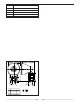
B.
Mounting Arrangements (see figure 1).
The speaker can be mounted on any relatively flat
surface. Conduit connection can be made to two 1/2"
threaded openings at the bottom of the housing or to 7/8"
knockout in rear of housing. A 1/2" conduit plug is supplied
for field installation if one of the 1/2" threaded openings is
not utilized. After the mounting location and mounting
method have been selected, proceed with the applicable
instructions below.
WARNING
Property damage, serious injury, or death could occur if an
accumulation of water, snow, dust, etc. resides in the speaker
projector, severely reducing or preventing operation of this
device. Mount the unit so speaker projector is pointed horizon-
tally or slightly downward.
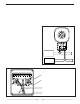
1. Flat Surface Mounting
a. Remove and retain the two screws that
secure cover to housing. Remove the cover.
b. Select the mounting location and place
rear of housing against mounting surface.
c. Using the mounting holes (two (2) inside
housing) as a template, scribe drill position marks on the
mounting surface. See figure 1 for mounting hole locations
and dimensions.
CAUTION
Before drilling holes in any surface, ensure that both sides of
surface are clear of items that could be damaged.
d. Secure the unit to a wooden mounting
surface with #10 x 1" wood screws. If mounting on a metal
surface, drill 13/64" diameter holes and secure the unit with
#10 screws, lockwashers and nuts.
e. Route power and supervision leads through
conduit to the audible signal. Install a 1/2" electrical connec-
tor at the bottom of the audible signal. Route wires through
conduit and electrical connector into the audible signal
INSTRUCTION SHEET
SPHPSPHP
SPHPSPHP
SPHP
POWERTONE® SPEAKERSPOWERTONE® SPEAKERS
POWERTONE® SPEAKERSPOWERTONE® SPEAKERS
POWERTONE® SPEAKERS
(With or without Strobe Warning Light)
C
256882 0209