
Installation Instructions


RBS 884 Pico (1900 MHz) Radio Head Installation
PCM Interface
Connnector Ports
RHI Customer
Interface
AC Alternating Current
LED Light Emitting Diode
PCM Pulse Code Modulation
RHI Radio Head Interface
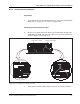
Front View
Power/Fault LED
AC Receptacle
AC Power Cord
Tamper-Resistant
Seal
Figure 4-19. Radio Head AC Power Cord and AC Receptacle
13. Attach a spring-type ferrite to the AC power cord and position the
ferrite as close to the Radio
Head as possible.
14. When power is applied to the Radio Head, a self-test is performed. The
Power/Fault LED on the left corner of the Radio Head flashes red at a
3 Hz rate during the self te
st.SeeFigure4-19onpage4-40forthe
location of the Power/Fault LED.
Connecting Radio Head 2
15.
Warning!
Do not route the cable ac
ross the front of the Radio Head. Use the
cable tray on top of the mounting bracket.
4-40 2/1531-AE/LZB 119 3834 Uae Rev PA6 2001-04-04