Rhein Tech Laboratories, Inc. 360 Herndon Parkway Suite 1400 Herndon, VA 20170 http://www.rheintech.com Appendix K: Client: M/A-COM, Inc. Model: OpenSky 800 MHz Base Station ID’s: BV8MBS800B075/3670A-MBS800B Standards: FCC Part 90/IC RSS-119 Report #: 2008072 User Manual Please refer to the following pages.
Installation Manual MM102225V1 Rev.
MM102225V1, Rev. B MANUAL REVISION HISTORY REV DATE REASON FOR CHANGE A 2003 Initial release. B Jul. 2005 Changed Accuracy Test, Step 7, added Caution added footnote. M/A-COM Technical Publications would particularly appreciate feedback on any errors that might be found in this document, and suggestions on how it could be improved. Submit your comments and suggestions to: Wireless Systems Business Unit M/A-COM, Inc.
MM102225V1, Rev. B TABLE OF CONTENTS Page 1.0 1.1. 1.2. 1.3. 1.4. 1.5. 1.6. 1.7. 2.0 GENERAL INFORMATION.............................................................................................................................6 INTRODUCTION .............................................................................................................................................6 REFERENCE MATERIAL..........................................................................................................
MM102225V1, Rev. B TABLE OF CONTENTS Page 6.1.1 12dB SINAD Receiver Sensitivity ........................................................................................................... 43 6.2 ANALOG PERFORMANCE TESTING OF TOWER TOP AMPLIFIERS ................................................... 46 6.2.1 Tower Top Amplifier Performance Test.................................................................................................. 46 6.
MM102225V1, Rev. B TABLE OF CONTENTS Page APPENDIX L.................................................................................................................................................................96 RECORDED DATA SHEET ......................................................................................................................................96 FIGURES Figure 3-1: Figure 3-2: Figure 3-3: Figure 3-4: Figure 3-5: Figure 3-6: Bolt Assembly Hardware...................................
MM102225V1, Rev. B 1.0 GENERAL INFORMATION1 1.1. INTRODUCTION This manual specifies procedures for installing and testing OpenSky® Base Station/Tower equipment racks at a communication site. This manual is intended for M/A-COM and contracted personnel responsible for supervising or conducting the equipment rack installation process. Before attempting to install or checkout this equipment, become familiar with the contents of this manual.
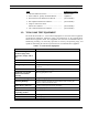
MM102225V1, Rev. B Title Publication Number • OE-100 Outdoor Enclosure........................................ MM102226V1 • M/A-COM, Inc. Quality Standards Manual............... GQM0221 • Rack Breaker Panel Maintenance Manual ................. (Not Available) • RX Amplifier Maintenance Manual .......................... (Not Available) • Duplexer and Power Sensor Maintenance Manual ................................................. (Not Available) TX Combiner Maintenance Manual ..............
MM102225V1, Rev.
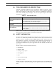
MM102225V1, Rev. B 1.4. TOOLS REQUIRED FOR SPECIFIC TASK Generally, professional judgment can be used about the fitness of a tool for a given purpose. In some cases, however, specific tools must be used to complete installation steps properly. Failing to use the correct tool in these cases could damage equipment or leave crucial assembly steps incomplete.
MM102225V1, Rev. B The safety guidelines and precautions presented in this manual do not replace M/ACOM's specific requirements. The primary responsibility for health and safety standards, practices and guides lines in a M/A-COM project lies with the Environmental, Health & Safety (EHS) department.
MM102225V1, Rev. B 11. DO NOT operate equipment with damaged power cords or plugs - replace them immediately. 12. DO NOT operate this product in an explosive atmosphere. 13. To reduce risk of electric shock, unplug unit from outlet before attempting any maintenance or cleaning. 14. DO NOT operate this product with covers or panels removed. Refer all servicing to qualified service personnel. 15. Use only fuses of the correct type, voltage rating and current rating as specified in the parts list.
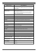
MM102225V1, Rev. B 1.7. OpenSky BASE STATION EQUIPMENT SPECIFICATION (General) Type: Indoor Cabinet 83 Inch Floor Mount Size: Height: 83 inches (77 inches usable) Width: 22 inches Depth: 24 inches Number of Rack Units (RU): 44 RU available Weight (Approximate) Depending on the number of RF channels installed, the weight could range from 350 to 500 LBS for the rack with the HPA's. Usually Rack #2 is the HPA rack.
MM102225V1, Rev. B 2.0 SITE PREPARATION 2.1 INTRODUCTION This section provides instructions for preparing the site and other installation items, which must be completed prior to installing OpenSky Communication equipment. The areas covered include the following: Antenna System - This includes installation of the antenna tower, receive and transmit antennas, tower top amplifier and the installation of the transmission lines from the antenna to the tower top amplifier to the equipment shelter.
MM102225V1, Rev. B 2.2.2.2 Minimum Bending Radius Always adhere to the minimum bending requirements provided by the manufacturer. For Andrew Products, the values are: CABLE SIZE BENDING RADIUS 1/4-inch 1-inch (25 mm) 1/2-inch 1.25-inch (32 mm) 7/8-inch 10-inches (250 mm) 1-5/8-inch 20-inches (510 mm) 2.2.2.3 Hoisting Grips Hoisting grips provide the means to attach a lifting mechanism to the coaxial cable without damaging the cable.
MM102225V1, Rev. B Adapters for each antenna system are selected when ordering the system. If the coaxial cable must be attached to a structure that is not compatible with any of the above hangers or adapters, then additional materials or other special considerations may be required. To secure 1/4-inch or 1/2-inch vertical or horizontal coaxial cables of any size, use UV resistant, black nylon cable ties. 2.2.2.
MM102225V1, Rev. B Although the temperature requirements for individual pieces of trunked equipment may be broader, when several units are assembled together in a cabinet more heat is generated. Because of this condition, the ambient room temperature outside the cabinet must be lowered to ensure the temperature inside the cabinet does not exceed the limits for the equipment. 2.4.3 Electrical Power Normally, OpenSky equipment is powered by –48 VDC.
MM102225V1, Rev. B 4. Record the design gain of the antenna. 5. If the antenna is directional, record the bearing of the main lobe, using the magnetic declination for True North. If it is Omni, write "Omni" in the data entry line. 6. Record the height of the antenna above ground. 7. Confirm that cable-hoisting grips were installed as required to prevent damage to the coaxial cable. Hoisting grips should have been installed at the antenna end of the cable plus one for each 200 feet of cable length. 8.
MM102225V1, Rev. B 3.0 BASE STATION INSTALLATION The following sections present the steps required for installation of populated OpenSky base station equipment racks at a communications site. To a certain extent, installations must be planned site-by-site, because of the wide variety of installation conditions and configurations. Installers will encounter many types of equipment enclosures and tower site equipment configurations.
MM102225V1, Rev. B • 3.3 Connecting the power supply and site subsystems external to the OpenSky equipment racks SECURING EQUIPMENT RACKS TO THE FLOOR Move the racks into the designated positions and prepare to bolt them to the floor. In rare cases, bolting to the floor may be prohibited. In those cases, bolt the racks to each other for stability. Procedure: 1. Using a template, mark bolt locations for each equipment rack to be installed. 2.
MM102225V1, Rev.
MM102225V1, Rev. B BOLT ASSEMBLIES Figure 3-4: Bolt Assembly Used to Bolt Rack to Concrete Floor • For wood floors, use a lag bolt with an insulating nylon washer under the head to bolt the racks to the floor. Insulating phenolic strips under the racks are not required. No pilot hole is needed on wood floors. • For raised floors, the rack attachment procedure is quite different. The first and last racks in the row are bolted to the sub-floor as shown below.
MM102225V1, Rev. B 3.4 CABLING EQUIPMENT RACK COMPONENTS Once the racks have been installed, interrack cable connections must be made, and racks must be connected to a power source and grounded, as well as connected to external communications sub-systems such as antennas. Follow this procedure in accordance with M/A-COM, Inc. Quality Standards Manual GQM0221. Possible rack-ups of equipment cabinets are shown in Figures 6 and 7.
MM102225V1, Rev. B 44 RU--- 40 RU--- 35 RU--- 1 RU RACK LABEL 3 RU RACK BREAKER PANEL 2 RU BLANK 2 RU RX AMPLIFIER 3 RU TT AMP CONTROLLER 30 RU--- Rack total height is 83" of which 77" is usable.
MM102225V1, Rev. B Figure 3-8: HPA RF Input Connection Figure 3-9: DCX RF Output Connection 2. Racks that hold the HPA's have two large unconnected wire bundles covered with a split loom. Pull these bundles to the adjacent rack, which contains the DCXs and the Base Station Alarm Module4 (see Figure 3-10: Wire Bundles with DCX and Base Station Alarm Wiring).
MM102225V1, Rev. B ION Alarm Bundle with Lock-n-Mate Connectors Figure 3-10: Wire Bundles with DCX and Base Station Alarm Wiring (This figure is for the ION Alarm only. The DPS Alarm uses punchblock connections.) 3. Included in the wire bundle above, is a wiring harness with the female half of a MATE-N-LOK® connector.
MM102225V1, Rev. B 4. The remaining cables in this wiring bundle are data cables that attach to each DCX. Dress these cables into the cable tray. Each data cable terminates in a pigtail with an RS-485 connector on both the main cable and its pigtail. Following the labels on each data cable, plug the main cable and its pigtail into the two RS-485 ports on each DCX.
MM102225V1, Rev. B Multi-Coupler port (see Figure 3-14: Cable Connecting the Tower-Top Amplifier Control Box to the Input port of the Multi-Coupler). Figure 3-14: Cable Connecting the Tower-Top Amplifier Control Box to the Input port of the MultiCoupler 3.4.2 Connecting Power Source and External Equipment Once rack-to-rack cables have been connected, the racked equipment in the enclosure must be connected to external equipment and to the power source.
MM102225V1, Rev. B 3.4.3 Connect Cabling for the Power Source 1. Run two DC power cables (#6 insulated red connected to -48 volts) and ground (DC return insulated black) from the site's -48VDC Distribution Panel (see Figure 3-17: 48 Volt Breaker Distribution Panel of the DC Power Supply - Red Wire5 and Figure 3-18: DC Return Distribution Bar - Black Wires) to each rack, attaching the cables to the racks.
MM102225V1, Rev. B Figure 3-18: DC Return Distribution Bar - Black Wires 2. If not already labeled, label OpenSky circuits in the breaker panel to identify each rack (see Figure 3-19: Properly Labeled OpenSky Circuit Breakers in the Distribution Panel - OpenSky Rack 1, OpenSky Rack 2, etc.) Figure 3-19: Properly Labeled OpenSky Circuit Breakers in the Distribution Panel 3.
MM102225V1, Rev. B 3.4.4 Connect Grounding Cables to Equipment Racks Attach a ground cable to each rack. 1. Run #6 Green grounding cable (stranded copper) from each rack ground directly to the single-point ground bar in each enclosure. All bends in the grounding cables must be < 70-degrees. All bends in the grounding cables must have minimum bend radius of 8 inches. CAUTION See the M/A-COM Quality Standards Manual (GQM0221) for more information. 2.
MM102225V1, Rev. B 3. Route the ground cables together and maintain at least two inches (2") spacing between the ground cable bundle and other types of cables. 3.4.5 Connect Antenna Cables to Equipment Racks Attach the antenna cables to the communications equipment. 1. Prior to the communications equipment installation, one or two antennas will have been installed at the site. The antenna cables will have been terminated inside the enclosure onto a metal plate (ground plane).
MM102225V1, Rev. B 3.4.6 Connect the T1 Network Connect the high-speed digital T1 (telephone) network Interface to the Site Access Server as defined by the Site Deployment Order. In most installations, this connection goes to microwave equipment. NOTE 3.4.7 Site Clean Up Before leaving, remove any debris, such as wire clippings, metal shavings, dust mounds, etc. from the site. 3.
MM102225V1, Rev. B 4.0 SITE TEST PROCEDURES 4.1 PURPOSE AND SCOPE This section describes post installation tests required for compliance testing of the M/ACOM Wireless Systems OpenSky Digital Base Station. This section defines and details the test plan and methodology for each test. Objective: This test confirms a base site receive channel is not corrupted by site specific noise or interference. Site installation and site gain optimization should be completed before this test is performed.
MM102225V1, Rev. B 4.2 OVERVIEW OF OPENSKY BASE SITE EQUIPMENT An OpenSky base station consists of a variety of products and includes radio transmitting and receiving equipment, RF distribution equipment and network communications system interface equipment. OpenSky is a digital system and has some significant differences in terms of fixed network connectivity to that commonly seen with conventional analog systems.
MM102225V1, Rev. B 4.4 PREPARATION To prepare for the start of testing, it is important that all test equipment be powered up now and allowed to thermally stabilize. Begin by powering up the Communications Test Set HP 8920. Record the specifics of each of the system components. Before testing the complete system, verify that the system is cabled correctly.
MM102225V1, Rev. B 4.7 INSPECTION In this section, the location of the installation is recorded and equipment configuration parameters are verified against the As Built. In addition, general workmanship and quality of assembly and installation are inspected NOTE Only selected parameters are checked against the recorded factory configuration as all parameters are programmed into equipment before leaving the factory and hence should not require to be modified. 4.7.
MM102225V1, Rev. B 4.7.2 ALARM CABLING 2. Interrack Cabling ACTION MISCELLANEOUS The photograph to the right shows the location of the inter-rack alarm interconnect cable. Verify that it has been connected as shown where the circle is located. RECEIVE MULTICOUPLER INPUT 3. ACTION MISCELLANEOUS The photograph to the right shows the source and destination points for the receive Multicoupler feed. Verify that it is connected as shown.
MM102225V1, Rev. B HPA RF INPUT ACTION 4. The photograph to the right shows the destination point for the HPA RF Input. Verify that they are connected as shown. HPA CONTROL CONNECTION 5. 38 ACTION The photograph to the right shows the destination point for the HPA control cable. Verify that they are connected as shown.
MM102225V1, Rev. B 4.7.3 RACK POWER CONNECTION 6. New Cabling ACTION MISCELLANEOUS The photograph to the right shows the connection points and polarity of the DC power connection to each power distribution panel. Verify that they are connected as shown. Black Red Note: The red cable is the most negative, i.e. -48VDC. The black cable is the return. RACK GROUNDING 7. ACTION MISCELLANEOUS The photograph to the right shows the connection point for rack to halo grounding.
MM102225V1, Rev. B SYSTEM COMMUNICATIONS ACTION MISCELLANEOUS The photograph to the right shows the in-rack connection point for T1 communications. 8. The destination of this connection will vary by site; however, verify that a modular style plug wired (T568B) is used to connect the site communications interface with the base site T1. If equipped with ISM Backhaul, the Orange cable is the 10BaseT connection to the ISM Backhaul Router. Note: Actual cables may be different colors.
MM102225V1, Rev. B TRANSMIT ANTENNA CONNECTION ACTION 11. The photograph to the right shows the in-rack connection point for the system transmit antenna. Verify that the jumper cable is present and disconnect it from the Bird Power Monitor output. DUPLEX ANTENNA CONNECTION ACTION 12. MISCELLANEOUS MISCELLANEOUS The photograph to the right shows the in-rack connection point for a duplexed system. Verify that the jumper cable is present and disconnect it from the "T" shaped connection.
MM102225V1, Rev. B 5.0 EQUIPMENT CONFIGURATION The objective of this procedure is to verify that base station equipment has been correctly programmed for the site at which it is installed. Testing involves connecting a laptop computer to each piece of equipment and interrogating and recording configuration files. A record of the configuration files will be shipped with the radio rack.
MM102225V1, Rev. B 6.0 PERFORMANCE TESTING6 This series of tests characterizes the receive performance of the Base Station in terms of its absolute sensitivity and its sensitivity relative to the local noise floor at the installed site. The base station is capable of providing a raw discriminated output to support analog receive testing. The output is provided on the "Q" Transmitter output of the BSC when the base station is in output mode 0.
MM102225V1, Rev. B STEPS ACTION 3. To place the DCX in Analog Mode, enter the sequence of commands indicated by bold script in the example seen to the right. 4. Repeat Steps 1 and 2 for all other DCX units. 5. Ensure that the DCX and HPA under test are powered up and the HPA is offline. On the HP 8920, select the RF GEN screen and set the following configuration, (see adjacent photo): RF Gen Freq: Set for the receive frequency of the RF path under test (45MHz below the Transmit Frequency) . 6.
MM102225V1, Rev. B STEPS 8. ACTION MISCELLANEOUS Select the RF GEN screen and place the cursor on the Amplitude field. Configure test as follows: 9. 7 • Verify HP 8920 RF IN/OUT port is connected to the antenna port of the TTA Controller. • Disconnect the TX Q cable from the DCX under test. • Connect a Test Cable between the TX Q port under test and the Audio In Hi port of the HP 8920. 10. Adjust the volume control on the HP 8920 until the 1kHz test tone is audible. 11.
MM102225V1, Rev. B 6.2 ANALOG PERFORMANCE TESTING OF TOWER TOP AMPLIFIERS This single channel measurement is performed using external antenna coupling between the transmit and receive antennas to deliver a test signal to the TTA. A SINAD System level test is performed with the TTA "On" and "Off" to measure the receive system improvement provided by the TTA. This is a relative measurement the difference between the "On" and "Off" measured value represents the system improvement provided by the TTA.
MM102225V1, Rev. B 6.3 TOWER TOP LOW NOISE AMPLIFIER (TTA) GAIN MEASUREMENT (REQUIRED) The purpose of this test is to measure the gain of the TTA. The method will be to inject a test signal into the transmit jumper cable using a receive channel frequency. This signal will be coupled from the transmit antenna to the receive antenna and a reference power level measurement will be made with the TTA “On” and a second measurement will be made with the TTA “Off”.
MM102225V1, Rev. B STEPS 8 ACTION 6. Record the power level as indicated in the HP 8920 Spectrum Analyzer Lvl field. Enter this value in the TTA Gain table, column 2 for TTA “On”8. 7. Turn the Power Switch on the front of the TTA Control Panel to the “Off” position. 8. Record the power level as indicated in the HP 8920 Spectrum Analyzer Lvl field. Enter this value in the TTA Amplifier Gain table, column 2 for TTA “Off”. 9. Subtract the recorded “Off” Lvl from the “On” Lvl. 10.
MM102225V1, Rev. B 6.4 ANTENNA 20DB QUIETING TEST (MANDATORY) Objective: This test measures the susceptibility of the site to de-sense resulting from site-specific interference. STEPS 1. ACTION MISCELLANEOUS On the HP 8920, select the RF GEN screen and set the following configuration: RF Gen Freq: Set for the receive frequency of the RF path under test. (45MHz below the Transmit Frequency recorded in data collection sheet. The set frequency will be in the range from 806-824 MHz.
MM102225V1, Rev. B STEPS ACTION Configure test as follows: • • 4. • • • • 9 Connect the 30dB Directional Coupler to the input of the receive multicoupler. Connect the RF IN/OUT connector of the HP 8920 to the coupler port labeled as TO ANALY. Connect the 50-Ohm terminator to the ANT/TERM port of the coupler. Connect Duplx/SPL port to Multicoupler Input. Disconnect the Tx Q cable from the controller module of the DCX. Connect a Test Cable between the Tx Q port and the Audio In Hi port of the HP 8920.
MM102225V1, Rev. B STEPS ACTION 8. Record the new 20dB quiet value of AC Level on worksheet together with its associated RF input level10. 9. Replace the 50-Ohm Terminator with the main receive antenna feed. The indicated value of AC Level will increase. 10. Increase the RF input Amplitude to recover the reading recorded on the worksheet. 11. Calculate the difference between readings obtained with Antenna versus the 50-ohm Terminator to obtain the 20dB de-sense value.
MM102225V1, Rev. B 6.5 BASE STATION TRANSMIT (BSX) FREQUENCY ACCURACY TEST (MANDATORY) Objective: The purpose of the Base Station Frequency Test is to verify that the DCX is operating on the allocated frequency and compliant with the FCC specifications. STEPS ACTION 1. Connect the PC to the DCX TERMINAL port. MISCELLANEOUS offline ; 2.
MM102225V1, Rev. B 6.6 TRANSMIT DEVIATION (MANDATORY) Objective: The objective of this test is to ensure that the transmit deviation is correctly adjusted. STEPS ACTION 1. Verify that the HPA transmit Enable/ Disable switch is set to the Disable position for all HPA’s. 2. Select the RF GEN screen and set the Amplitude field to Off by pressing the ON/OFF / (YES) key. MISCELLANEOUS Select the AF Analyzer Screen on the HP 8920 and configure the following parameters: 3.
MM102225V1, Rev. B 6.7 TX POWER CALIBRATION (MANDATORY) Objective: The following procedure sets the output power level at the final rack RF transmit port based on the transmit Antenna/Feedline Gains and Losses shown in the following examples. STEPS ACTION MISCELLANEOUS Example of Calculating and Setting an ERP of 50dBm: 1. Calculate the required HPA TX Power setting based on the required site ERP. HPA TX Level may be calculated as seen on the right.
MM102225V1, Rev. B STEPS ACTION Press the Enter key on the laptop keyboard. 9. MISCELLANEOUS Example: buck40:14 buck40-bs1> The status information on the right will be displayed on the PC console application. Similar to the text found on the right. Setting the HPA TX Power 10. Enter the command: at@hpapowerN [CR] 11. Set the HPA Disable/Enable switch to Enable. 12. The HPA will send the message shown on the right via the DCX to the console display and start transmitting. 13.
MM102225V1, Rev. B STEPS ACTION 18. Complete the summary acceptance table confirming that the HPA transmit power for each channel was set to provide the site specified ERP. 6.8 MISCELLANEOUS HPA TX POWER BENCHMARKS – BIRD VSWR –57DBM PORT (REQUIRED) Objective: The objective of this test is to provide a reference power measurement for each transmitter at the Bird Power Monitor (VSWR) –57dBm Port with the Bird Power Monitor Output Port connected to the TX Antenna.
MM102225V1, Rev. B STEPS ACTION MISCELLANEOUS Select the AF ANL screen and configure the following settings: 4. • TX Power: dBm (Average 10) • AF Anl In: FM Demod • De-Emphasis: Off • Detector: Pk+-/2 5. Set the HPA Enable/Disable switch to the Enable position. 6. Measure and record the TX Power from the HP 8920 AF Analyzer screen on the data collection sheet, factoring in the additional loss of the test cable16. 7.
MM102225V1, Rev. B STEPS 11. 18 ACTION Record18 the results in table provided with the data worksheet.
MM102225V1, Rev. B 7.0 OPERATIONAL TESTING 7.1 STANDALONE SITE ACCEPTANCE (MANDATORY) Objective: To verify correct functionality of the site in a standalone mode of operation. Successful completion of this series of tests together with all preceding mandatory tests will allow full operation of the site in standalone or repeater mode. This stage of site certification permits its use in the event that backhaul communications are not available. 7.1.1 STEPS ACTION 1.
MM102225V1, Rev. B STEPS ACTION 6. Disable all HPA’s except RF channel under test. Select the RF channel under test (C. U. T.) and different talk group for both radios. Key the radio transmitters simultaneously and verify both stay on the same RF channel. Repeat for all RF channels allocated to site. 7. Enable all HPA’s. Select different RF channels and the same talk group for both radios.
MM102225V1, Rev. B STEPS ACTION 3. Check the rear panel of the Cisco 3600 access server and observe whether the Carrier Detect LED is lit and the LOCAL and REMOTE ALARM LED’s are off. 4. Connect the PC to the CON port of the Cisco 3600 access server. This connector is located on its front panel. MISCELLANEOUS buck40sas>ping 10.136.10.2119 Sending 5, 100-byte ICMP Echoes to 10.136.8.10, timeout is 2 seconds: !!!!! 5.
MM102225V1, Rev. B 7.3 T1 QUALITY LINK Objective: The Cisco 3600 provides comprehensive monitoring capabilities for the T1 port that carries data traffic over the communications backbone. The showcontroller command accumulates statistics over sixteen 15-minute intervals. This test does not form part of the site acceptance testing but is included as a diagnostic tool to aid resolution of link related issues. STEPS 1.
MM102225V1, Rev.
MM102225V1, Rev. B 7.4.1 Power Failure STEPS ACTION 1. Connect the PC to the TERMINAL port of the DCX. 2. Type the command: opred ? [CR] MISCELLANEOUS Manadabs2> opred? OPRED: BssN Status: Socket: 7 MCAddr: 225.1.2.35[6801] Cond: 1 OPRED: SasN Status: Socket: 8 MCAddr: 225.1.1.32[6802] Cond: 1 OPRED: Device Status: BSC:Up HPA:Keyed BSX:Up BSIB:Undef OPRED: Expected/Actual Peers - Normal: 1/1 Standbys: 0/0 MCD: 2 3. The DCX will respond with the information on the right.
MM102225V1, Rev. B 7.4.2 STEPS 1. 2. Multi Site Trunking ACTION MISCELLANEOUS Verify all HPA ENABLE/DISABLE switches to the ENABLE position. Configure two mobile radios using the station parameters of the site under test. 3. Power cycle the radios using their front panel power switch. 4. Unit to Unit Call 5. Trunk Call to another site. 6.
MM102225V1, Rev. B 8.0 COMMON TERMS The following brief explanations describe OpenSky Base Station rack components and define other common terms: Table 8-1: Common Terms TERM Alarm Module ACRONYM OR ALIAS ION DEFINITION Environment and equipment monitor with network or pager alarm capability, providing detection of out-of-specification conditions. Device used initially: ION Networks, Inc.: Sentinel 2000 Slimline Antenna Device that transmits or receives electromagnetic radiation at radio frequencies.
MM102225V1, Rev. B TERM InterModulation Rejection ACRONYM OR ALIAS IMR DEFINITION The reject to the production, in a nonlinear element of a system, of frequencies corresponding to the sum and difference frequencies of the fundamentals and harmonics thereof that are transmitted through the element. Control unit used to process data from the tower-topmounted Industrial, Scientific, and Medical (ISM) transceiver. ISM Controller (BackHaul Router) (ISM is a license-free RF communications band; 2.4 GHz and 5.
MM102225V1, Rev. B TERM ACRONYM OR ALIAS Prevents reflection of RF energy back into the RF source (the transmitter). TX/RX Isolator Voltage Standing Wave Ratio Monitor 68 DEFINITION VSWR Monitor Placed in the antenna feed circuit, it continuously monitors the forward and reverse power using a directional coupler.
MM102225V1, Rev.
MM102225V1, Rev. B APPENDIX A ATTACHING MIL-SPEC (MS) CONNECTOR TO END OF CONTROL CABLE/SOLDERING TOWER TOP AMPLIFIER CONTROL CABLE22 Detail “A” A – PRI ALARM (Blue) A B – SEC. ALARM (Green) B C – ALM POWER (Red) E C D – METER LINE (White) D E - GROUND 22 Taken from M/A-COM, Inc. Drawing No.
MM102225V1, Rev.
MM102225V1, Rev. B APPENDIX B CONNECTING A PC TO A BASE STATION23 There are three ways to connect a personal computer to OpenSky Base Station equipment: 1. Direct connection to the RS-232 port of the device under test. 2. Direct connection to the Console Port of the Access Server and telnet to the device under test. 3. Direct connection to the Ethernet port of the Access Server and telnet to other devices.
MM102225V1, Rev.
MM102225V1, Rev. B APPENDIX C EQUIPMENT SERIAL NUMBERS24 RACK 24 EQUIPMENT 1 Alarm 1 DCX 1 1 DCX 2 1 DCX 3 1 Cisco 2 Bird Power Mon 2 TTA Controller 2 HPA 1 2 HPA 2 2 HPA 3 1 RCVR Multicoupler SERIAL NUMBER Taken from M/A-COM, Inc. Drawing No. GTP-0296, Rev. A.
MM102225V1, Rev.
MM102225V1, Rev. B APPENDIX D SITE ACCESS SERVER CONFIGURATION25 PARAMETER & VALUE EXPLANATION buck40sas#show run Building configuration Current configuration: ! version 12.
MM102225V1, Rev. B PARAMETER & VALUE EXPLANATION ! process-max-time 200 ! interface Loopback0 ip address 10.136.24.158 255.255.255.224 no ip directed-broadcast ip pim dense-mode no ip mroute-cache ! interface Loopback1 ip address 10.136.24.190 255.255.255.224 no ip directed-broadcast ! interface FastEthernet1/0 ip address 10.136.24.222 255.255.255.
MM102225V1, Rev.
MM102225V1, Rev. B PARAMETER & VALUE EXPLANATION no ip address no ip directed-broadcast async mode interactive ! interface Async13 no ip address no ip directed-broadcast async mode interactive ! interface Async15 ip unnumbered Loopback1 no ip directed-broadcast async mode dedicated ! interface Async16 ip unnumbered Loopback1 no ip directed-broadcast encapsulation ppp shutdown async mode dedicated ! ip classless ip route 10.136.8.0 255.255.252.0 Serial1/0:0 ip route 10.136.24.129 255.255.255.
MM102225V1, Rev.
MM102225V1, Rev.
MM102225V1, Rev.
MM102225V1, Rev.
MM102225V1, Rev. B APPENDIX F TYPICAL BASE STATION CONFIGURATION27 manadabs2> at&v BSC INFORMATION: S/N: 000000010005 BSC INFORMATION: BSC S/W Version: BSC-1000 Version OTP 4.00 Sep 28 1999 14:58:02 BSC INFORMATION: BSC H/W Version: 50 MHz NGP Rev B with 1M of Memory BSC INFORMATION: M/A-COM HPA Version: 0.
MM102225V1, Rev. B RRM Cell Configuration Epoch: 30[1e] RRM Quality Parameters Epoch: 120[78] RRM RC Roaming Epoch: 10[a] RRM RC Roaming Parameters: 80[50] 40[28] 2[2] 25[19] 10[a] RRM RC Utilization Epoch: 0[0] RRM Utilization Roaming Parameters: 10[a] 40[28] 0[0] 60[3c] 30[1e] RRM Deactivation Roaming Parameters: 4[4] NMS Port: 6100[17d4] Deviation Scale Factor: 1.
MM102225V1, Rev. B Dispatch Network Netmask: 255.255.240.0 Peer Port: 6800[1a90] Redundancy SAS Multicast Address: 225.1.1.32 Redundancy SAS Multicast Port: 6802[1a92] Redundancy BSS Multicast Address: 225.1.2.
MM102225V1, Rev. B Voice Group Add: 16: 504 10 0 Voice Group Add: 17: 505 10 0 BSIB is present: 0[0] BSIB should key: 0[0] ** NOT USED **: 0[0] BSIB VSWR Alarm Levels: 0.000 1.200 0.000 0.000 0.000 1.200 BSIB power Alarm Levels: 0.000 0.000 0.000 0.000 0.000 0.
MM102225V1, Rev. B APPENDIX G TVARB STATUS28 TVARB show the status of the Transmit Voice Channel ARBitration (TVARB) process. Returned parameters provide useful insight to voice channel access information allowing system problems to be readily diagnosed.
MM102225V1, Rev. B Cable 1 Cisco black RJ45 to RJ45 Modular Cisco Terminal Adapter RJ45 to 9-Pin D Shell (F) Cables 2 & 3 Qty 2 BNC to N for in rack distribution losses. Qty1 N-N (F/F) barrel for in rack distribution losses HPA output power Cables 2 & 3 SMA (F) to N (M) to attach to HPA N F-F Barrel to attach to high power side of load.
MM102225V1, Rev. B APPENDIX H VERIFICATION TESTING – TRANSMIT FILTER TUNING29 Installed Site Cavity Tuning Procedure should also be consulted for Filter Tuning. 1. Installed Site Cavity Tuning Procedure. 2. Power on Agilent® 8920. Select RF GEN from TO SCREEN. 3. Set RF Gen Freq to frequency cavity is to be tuned to. 4. Set AMPLITUDE to -10 dBm. 5. Set Output Port to RF Out. 6. Set AF Gen1 to Off. 7. Select SPEC ANL from TO SCREEN. 8. Select ANT from CONTROLS. 9. Set REFERENCE LEVEL to 0.0 dBm. 10.
MM102225V1, Rev.
MM102225V1, Rev.
MM102225V1, Rev.
MM102225V1, Rev. B APPENDIX K ANTENNA SYSTEM INSTALLATION CHECKLIST (One sheet per antenna per site) SITE ______________ ANTENNA ______________ INSPECTED BY ______________ DATE ______________ CHECKLIST: 1. Is this antenna for Transmit, Receive or GPS? 2. What is the make and model of antenna? TX GPS RX OMNI DIRECTIONA L 3. What is the type of antenna? ______________ 4. What is the design gain of antenna? ______________ 5.
MM102225V1, Rev.
MM102225V1, Rev.
INSTALLATION CHECKLIST Network Connectivity Ping the MIS1 and MIS2 servers located in the ROC.
MM102225V1, Rev.
M/A-COM Wireless Systems 221 Jefferson Ridge Parkway Lynchburg, Virginia 24501 (Outside USA, 434-385-2400) Toll Free 800-528-7711 www.macom-wireless.com Printed in U.S.A.