
Install Manual Part 2


24
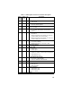
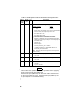
Table 2 - Radio Option Connector P3 Interface Description Con’t
DB-25
Pin No
(J100)
Pin No
(P3)
I/O Description
24 15 O
(1) HORN CONTROL At Signaling Mode
Display In Menu Action
On Enable
Off Disable
! When select “ON”(enable) and a correct T99 Individual
Call is received, the output of pin 15 is “low.”
! Horn Alarm ON : Low
!
Horn Alarm OFF: Open
(2) SPEAKER SELECT INTERNAL/EXTERNAL
! Enabling or disabling of the Internal/External Speaker
option is done by proper setting of an internal jumper in
the mobile radio.
! Internal: Low
! External: Open
! For relay control Io_max = 150mA
! **“HORN CONTROL” or “SPEAKER SELECT” is
selected by PC ProGrammer.
Note: Internal and external speaker do not operate
simultaneously.
12 16 I
Data Communication Input (Test Mode)
! TTL Level
25 17 O
Data Communication Output (Test Mode)
!
TTL Level
13 18 I
Ignition Sense
! 13.6VDC
!
Io_max = 100 mA
Internal Mic Mute (DB25-10) must be grounded when applying
audio to external Mic Input (DB25-19).
External Mic Input (DB25-19) has the same audio characteristics
as the Front Panel Mic Jack. External Mod Input (DB25-7) has
no pre-emphasis or modulation limiting.
NOTE