
Maintenance Manual


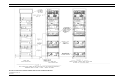


Table Of Contents

TABLE OF CONTENTS
2 MM101418V1 R1A
TABLE OF CONTENTS
Page
INTRODUCTION ................................................................................................................................................................. 3
APPLICATIONS ................................................................................................................................................................... 3
APPLICATION/ASSEMBLY DIAGRAMS
SINGLE STATION 69 IN CABINET WITH SITE PRO/SIM AA38-HRB 104 26 (SHEET 1)..................................... 5
MULTI-STATION 83 IN CABINET OR 86 IN OPEN RACK WITH SITE PRO/SIM
AA38-HRB 104 26 (SHEET 2)............................................................................................................................... 6
MULTI-STATION 69 IN/ 83 IN CABINET OR 86 IN OPEN RACK WITH SITE PRO ASSEMBLED
AA38-HRB 104 26 (SHEET 3)............................................................................................................................... 7
CABINET/RACK HARDWARE..................................................................................................................................... 8
ETHERNET HUB AA51-HRB 10426............................................................................................................................. 9
SITE SENTRY ASSEMBLY AA52-HRB 104 26........................................................................................................ 10
SIM SHELF AA53-HRB 104 26.................................................................................................................................... 11
MODEM/SITE SENTRY POWER SUPPLY SHELF AA54-HRB 104 26…………………………………… .......….12
GETC/SITE PRO SHELF AA55-HRB 104 26 ............................................................................................................. 13
STATION POWER SUPPLY AA56-HRB 104 26 ....................................................................................................... 14
MASTR III Tx P.A. AA57-HRB 104 26....................................................................................................................... 15
RF CONNECTIONS DIAGRAM FOR R.F. STATIONS CABINET/RACK ID38-HRB 104 26 (SHEET 1)............. 17
POWER CONNECTIONS DIAGRAM FOR R.F. STATIONS AND EQUIPMENT CABINET/RACK
ID38-HRB 104 26 (SHEET 2) .............................................................................................................................. 18
DATA CONNECTIONS DIAGRAM FOR R.F. STATIONS AND SIM/SITE SENTRY/SURE CALL
EQUIPMENT CABINET/RACK ID 38-HRB 104 26 (SHEET 3) ...................................................................... 19
DATA CONNECTIONS DIAGRAM FOR R.F. STATIONS ONLY CABINET/RACK ID
38-HRB 104 26 (SHEET4).................................................................................................................................... 20
ORION TU SHELF ASSEMBLY AD-SXK 107 3828................................................................................................. 21
MASTR III T.R. SHELF AA02-HRB 104 26 ............................................................................................................... 22
CONTROL EXTENDER BOARD 188D5338G1.......................................................................................................... 23
RF EXTENDER BOARD 188D5338G2........................................................................................................................ 23
GROUNDING STRAP INSTALLATION INSTRUCTIONS .......................................................................................24
CABINET GROUNDING……....………………………………………………………………………………………25
SITEPRO GROUNDING INSTALLATION INSTRUCTIONS ................................................................................... 26
19B801454P16 & P17.................................................................................................................................................... 27
19B801454P17 & P18.................................................................................................................................................... 27
19B801454P19 & P20.................................................................................................................................................... 27
19B801454P24 ............................................................................................................................................................... 27
CONTROL CABLE ASSEMBLY (PART OF POWER AMPLIFIER) 19B8017397P1............................................... 27
POWER CABLE (PART OF POWER AMPLIFIER) 19B801937P1............................................................................ 28
19B235871P1 ................................................................................................................................................................. 28
344A3052P1................................................................................................................................................................... 28
PARTS LIST........................................................................................................................................................................ 29
SAFETY NOTES
• The means of disconnecting power from a station cabinet is the cabinet power supply plug.
• When conducting repair/maintenance, disconnect the cabinet power supply plug from the AC source.
• In European applications, equipment must be installed in a closed cabinet.
• Only replace components with components specified by M/A-COM Private Radio Systems.
This manual is published by
M/A-COM Private Radio Systems, Inc
., without any warranty. Improvements and changes to this manual necessitated by
typographical errors, inaccuracies of current information, or improvements to programs and/or equipment, may be made by
M/A-COM Private Radio
Systems, Inc
., at any time and without notice. Such changes will be incorporated into new editions of this manual. No part of this manual may be
reproduced or transmitted in any form or by any means, electronic or mechanical, including photocopying and recording, for any purpose, without the
express written permission of
M/A-COM Private Radio Systems, Inc
.
Copyright 1992-2002, M/A-COM Private Radio Systems, Inc. All rights reserved.