
Maintenance Manual


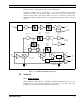


Table Of Contents
- INPUT AMPLIFIER NETWORK
- CRYSTAL FILTERS, IF AMPLIFIER
- INTEGRATED CIRCUIT AGC AMPLIFIER
- OSCILLATOR/MIXER/DETECTOR
- AUDIO AMPLIFIER
- SQUELCH
- FAULT DETECTORS
- VOLTAGE REGULATORS
- ADDRESS DECODER
- BUFFER AMPLIFIER U105
- RECOMMENDED TEST EQUIPMENT
- ALIGNMENT PROCEDURE
- CRYSTAL FILTER TUNING
- AUDIO AND DATA OUTPUT ADJUSTMENTS
- TROUBLESHOOTING
- ASSEMBLY DIAGRAM
- PARTS LIST
- IC DATA
- OUTLINE DIAGRAM
- SCHEMATIC DIAGRAM

DESCRIPTION
4 MM101886V1 R1A
2.0 DESCRIPTION
The MASTR III Receiver IF Module 19D902783G7/G11 provides amplification and
demodulation of the 21.4 MHz Intermediate Frequency (IF) signal as well as Automatic
Gain Controlled (AGC) 455 kHz outputs to the DSP Modem module(Figure 1 - 21.4
MHz Receiver IF Module). The IF Module also includes the receiver squelch circuitry.
However, it does not include de-emphasis or squelch audio gating circuits. Figure 2 –
21.4 MHz IF Module Block Diagram shows the functional operation of the IF Module.
The IF Module circuitry contains the following:
• A 50 ohm input impedance IF Amplifier
• A chain of four crystal filters and IF amplifier
•
A two stage AGC amplifier
•
A two stage balanced output IF amplifier
• An integrated circuit containing a crystal oscillator, mixer, limiter, and quadrature
detector
• A variable gain AF amplifier
• A squelch circuit
• A fault detector circuit
• An integrated circuit voltage regulator
• An address decoder
Figure 1 - 21.4 MHz Receiver IF Module