
Maintenance Manual


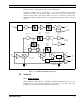


Table Of Contents
- INPUT AMPLIFIER NETWORK
- CRYSTAL FILTERS, IF AMPLIFIER
- INTEGRATED CIRCUIT AGC AMPLIFIER
- OSCILLATOR/MIXER/DETECTOR
- AUDIO AMPLIFIER
- SQUELCH
- FAULT DETECTORS
- VOLTAGE REGULATORS
- ADDRESS DECODER
- BUFFER AMPLIFIER U105
- RECOMMENDED TEST EQUIPMENT
- ALIGNMENT PROCEDURE
- CRYSTAL FILTER TUNING
- AUDIO AND DATA OUTPUT ADJUSTMENTS
- TROUBLESHOOTING
- ASSEMBLY DIAGRAM
- PARTS LIST
- IC DATA
- OUTLINE DIAGRAM
- SCHEMATIC DIAGRAM

CIRCUIT ANALYSIS
6 MM101886V1 R1A
3.4
OSCILLATOR/MIXER/DETECTOR
Integrated circuit U101 performs several functions. The 20.945 MHz crystal oscillator
provides local oscillator injection to the mixer in U101. This mixer converts the 21.4
MHz IF signal to 455 kHz. Capacitors C119 and C120 are oscillator feedback capacitors
and have been chosen to provide the proper capacitance for crystal Y100. The frequency
can be adjusted by means of L102. The proper oscillator output level is difficult to
measure directly without affecting the circuit operation. The level at TP3 should be
approximately 50 mVpk (Measured using a 10 megohm, 1lpF oscilloscope probe).
The mixer is internally connected to the crystal oscillator. Pins 1 and 20 of U101 are the
mixer input and output respectively. Typical mixer conversion voltage gain is
approximately 12 dB. The mixer output feeds the transistor Q100 IF amplifier circuit and
each analog switch, U102 and U103. The output from Q100 is routed to ceramic filter
FL100. In the 12.5 kHz bandwidth mode, analog switches U102 and U103 route the 455
kHz IF through FL101 to the U101 IF amplifier input. In the 25 kHz mode, the mixer
output is switched around FL101 by U102 and U103 and is then routed to the IF
amplifier input. In the four level FM mode, FL101 is bypassed as in the 25 kHz two level
mode. Ceramic filters FL101 and FL102 have a minimum 6dB bandwidth of 455 kHz
±6kHz.
The IF amplifier input is U101, Pin 18. The output at U101, Pin 16 is passed through an
attenuator consisting of resistors R143, R144, and R145 to ceramic bandpass filter
FL102, then to the limiter input at U101, Pin 14. The limiter output drives one input of
the quadrature detector via capacitor C129.
A Received Signal Strength Indicator (RSSI) is provided at U101, Pin 7. This indicator
signal is generated within the limiter circuitry and provides an output current proportional
to the logarithm of the input signal strength. This current develops a voltage across
resistor R141. The voltage varies from about 1.6 VDC for noise input, to about 2.4 VDC
for a 12 dB SINAD signal, to a maximum of about 4.7 VDC for a –75 dBm IF input
signal at J1. RSSI Buffer U200A provides buffering to eliminate loading effects on the
RSSI line. The RSSI line will provide a constant output level above a –75 dBm IF input
level, since the input to U101 is held constant by AGC from the DSP Modem module.
The quadrature detector provides a demodulated audio frequency output. One input to the
detector is internally connected to the limiter and is not externally available. The output
of the detector is at U101, Pin 9. Capacitor C145 provides lowpass filtering to remove
455 kHz feed-through. Ceramic resonator Y101 provides the frequency-selective
component needed for FM demodulation. Y101 replaces the typical LC resonant circuit
found in most quadrature detectors. In contrast to the typical LC network, Y101 requires
no adjustment. In the four level FM mode, the detector output of U101 is not used. The
detected audio output is derived by other circuitry in the base station.
Integrated circuit U101 general: The DC supply to U101 is provided through voltage
dropping resistor Rl04 to U101, Pin 6. The voltage drop across resistor R104 is used to
monitor the dc voltage on U101 for fault detection.
3.5
AUDIO AMPLIFIER
Operational amplifier U200C provides audio frequency amplification. The gain of
U200C is set by associated resistors, including variable resistor R203. Resistor R203
allows adjustment of the AF output level to 1 Vrms with a standard input signal to the