
User Manual Part 1

IC DATA
MM101271V1 R2A 129
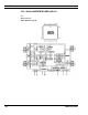
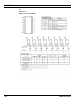
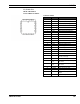
U9, U10 & U11
RF/PL/VDI Modem
Ericsson ROP 101 688/4C
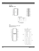
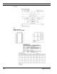
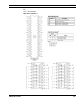
CONNECTIONS
Terminal Symbol Function
1 RE Read enable (active low)
2 EN Chip enable (active low)
3 RESOUT Reset output (active high)
4 AD0 Bi-directional address/data bus
5 AD1 Bi-directional address/data bus
6 AD2 Bi-directional address/data bus
7 AD3 Bi-directional address/data bus
8 AD4 Bi-directional address/data bus
9 AD5 Bi-directional address/data bus
10 AD6 Bi-directional address/data bus
11 AD7 Bi-directional address/data bus
12 ALE Address latch enable (active high)
13 VSS Ground
14 CLK1 Buffered oscillator output
15 VDD Power Supply
16 XTAL1 Oscillator input
17 XTAL2 Oscillator output
18 CLK2 640 kHz output
19 DRAIN Received data input
20 SAT/G1
Received SAT input/G1 enable
HC138 (active high)
21 TXDAT Transmit data output
22 RCVCLK/
Q2
Recovered clock output/Q2 output
for HC138
23 RCVDAT/
Q0
Recovered data output/Q0 output
for HC138
24 INT Interrupt request (active low o.d.)
25 RESIN Reset input (active high)
26 CS Chip select (active low)
27 CLK3/4 Transmit clock output/CLK 1/6
Output
28 WR Write enable (active low)