Operator’s Manual MM102341V1 P5A M7100IP Series Mobile Radios
SUPPLEMENTARY INFORMATION: At this time, the M7100IP mobile radio may not be operated while in a desktop station in the European Community since it does not meet immunity requirements when operated in this mode. The M7100IP mobile radio can be used in both trunked and conventional applications. ACKNOWLEDGEMENTS This device is made under license under one or more of the following US patents: 4,590,473; 4,636,791; 5,148,482; 5,185,796; 5,271,017; 5,377,229.
TABLE OF CONTENTS Page RF ENERGY EXPOSURE INFORMATION .............................................5 RF ENERGY AWARENESS, CONTROL, AND OPERATION ................5 COMPLIANCE WITH RF EXPOSURE STANDARDS ............................6 OPERATION SAFETY RECOMMENDATIONS.......................................8 TRANSMITTER HAZARDS ....................................................................8 SAFE DRIVING RECOMMENDATIONS ................................................9 OPERATING RULES AND REGULATIONS .......
TABLE OF CONTENTS Page INDIVIDUAL CALLS............................................................................. 45 SCAT OPERATION.............................................................................. 48 TELEPHONE INTERCONNECT CALLS.............................................. 48 MOBILE DATA ..................................................................................... 50 STATUS/MESSAGE OPERATION ...................................................... 53 EDACS CONVENTIONAL P1 SCAN .......
RF ENERGY EXPOSURE INFORMATION RF ENERGY EXPOSURE AWARENESS, CONTROL INFORMATION, AND OPERATION INSTRUCTIONS FOR FCC OCCUPATIONAL USE REQUIREMENTS BEFORE USING YOUR MOBILE TWO-WAY RADIO, READ THIS IMPORTANT RF ENERGY AWARENESS AND CONTROL INFORMATION AND OPERATIONAL INSTRUCTIONS TO ENSURE COMPLIANCE WITH THE FCC’S RF EXPOSURE GUIDELINES.
as a consequence of employment, the FCC requires users to be fully aware of and able to control their exposure to meet occupational requirements. Exposure awareness can be facilitated by the use of a label directing users to specific user awareness information. Your M/A-COM, Inc. M7100IP two-way radio has an RF exposure product label.
following. 1. The requirements of the antenna manufacturer/supplier included with the antenna. 2. Instructions in the Radio Installation Manual, including minimum antenna cable lengths. 3. The installation manual providing specific information of how to install the antennas to facilitate recommended operating distances to all potentially exposed persons. Use only the M/A-COM approved/supplied antenna(s) or approved replacement antenna.
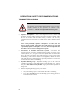
OPERATION SAFETY RECOMMENDATIONS TRANSMITTER HAZARDS The operator of any mobile radio should be aware of certain hazards common to the operation of vehicular radio transmitters. A list of several possible hazards is given: WARNING • Explosive Atmospheres – Just as it is dangerous to fuel a vehicle with the motor running, similar hazards exist when operating a mobile radio. Be sure to turn the radio off while fueling a vehicle.
• Liquefied Petroleum (LP) Gas Powered Vehicles – Mobile radio installations in vehicles powered by liquefied petroleum gas with the LP gas container in the trunk or other sealed-off space within the interior of the vehicle must conform to the National Fire Protection Association standard NFPA 58 requiring: The space containing the radio equipment shall be isolated by a seal from the space containing the LP gas container and its fittings. Outside filling connections shall be used for the LP gas container.
OPERATING RULES AND REGULATIONS Two-way FM radio systems must be operated in accordance with the rules and regulations of the local, regional, or national government. In the United States, the M7100IP Series mobile radio must be operated in accordance with the rules and regulations of the Federal Communications Commission (FCC). As an operator of two-way radio equipment, you must be thoroughly familiar with the rules that apply to your particular type of radio operation.
OPERATING TIPS The following conditions tend to reduce the effective range of two-way radios and should be avoided whenever possible: • Operating the radio in areas of low terrain, or while under power lines or bridges • Obstructions such as mountains and buildings • In areas where transmission or reception is poor, some improvement can be obtained by moving a few yards in another direction or moving to a higher elevation.
INTRODUCTION This manual describes how to use the M7100IP Series Mobile Radio. The M7100IP is a synthesized, microprocessor-based, high performance mobile FM radio providing reliable two-way communications in both the Enhanced Digital Access Communications System (EDACS®) trunking environment and conventional communication systems. In the EDACS or trunked system mode, the user selects a communications system and group.
USER INTERFACE The M7100IP operating controls are located on the radio's front panel (see Figure 1 and Figure 2). A keypad, vacuum florescent display for radio status information and a microphone jack are on the front panel. The front panel also provides a rotary SYSTEM/GROUP/CHANNEL knob, POWER ONOFF/VOLUME control, a ramp up/ramp down control, Scan add/delete control, and a SCAN ON-OFF control for scan operation.
Figure 1 - M7100IP Series Mobile Radio System Model Front Panel Figure 2 - M7100IP Series Mobile Radio Scan Model Front Panel 14
CONTROLS This section describes the buttons, keys and rotary knobs used to control the M7100IP Series Mobile Scan and System Model radios. All functions and controls of the Scan radio operate the same as the corresponding functions and controls on the System radio. The Scan radio is equipped with a 4-button keypad and the System radio is equipped with a 16-button keypad. Many of the control buttons and keys have or can be programmed to have a primary function and a secondary function.
The secondary function of the SCAN button is to toggle the keypad buttons between their primary function and their secondary function. SCAN ADD/DELETE This rocker type button is used to display the current SCAN status for a group/channel and then either add or delete the group/channel from the system scan list. INDICATORS Transmitter enabled - ON when the radio is transmitting. BuSY - On indicates a carrier is being received (the channel is busy).
KEYPAD The keypad is similar to a telephone keypad but with four (4) additional buttons on the side for a total of 16 keys. In addition to numbers (1-9, *, 0 and #), which is a secondary function, most of the keys have or can be programmed to have a primary function. A symbol or abbreviated word describing its primary function is labeled on the keycap. Each labeled keycap is associated with a radio feature (or primary function).
Optional Keycap Configuration The optional keycap package for the System radio includes sixty (60) additional keycaps (shown in the Key Descriptions section), which can be placed on any key location desired. Keep in mind, the keycap represents the primary function programmed for that key location. Key Descriptions MODE This key is used to enter the Conventional System selection mode. HOME This key returns the radio to the Home System/Group where it is programmed.
c C P D I E Serves several purposes depending on the operating mode. In trunked mode, the CLR button exits the current operation and removes all displays associated with it. The radio and display then return to the group receive state. In Conventional mode, pressing this button unmutes the receiver so activity on the selected channel can be monitored.
G* This key function is used in Conventional Mode to send G STAR emergency signaling. PA This key function enables and disables the Public Address feature. # DTMF keypad function. 1 thru 9 Keypad numbers. * DTMF Keypad function. Primary Functions (Quick Access) The secondary function of the k button is to toggle the keypad buttons between their primary function and their secondary function. When the secondary keypad is active, i.e.
DISPLAY The radio's display is shown in Figure 6. The two character lines are used to display system, group and channel names and also operational messages. Each line contains eight alphanumeric character blocks. See Figure 2 for a typical display. Figure 6 – M7100IP Series Mobile Radio Display RADIO STATUS ICONS Status icons are indicators that show the various operating characteristics of the radio. The icons appear on the first line of the display.
MESSAGES During radio operation, various messages are displayed on either line 1 or line 2. Typical messages include control channel status information, such as system busy or call denied, or messages associated with the radio's operation, (i.e. volume adjust). These messages are described as follows: Table 2 – Display Messages MESSAGE NAME DESCRIPTION QUEUED Call Queued Trunked mode only. Indicates the system has placed the call in a request queue. SYS BUSY System Busy Trunked mode only.
MESSAGE NAME DESCRIPTION SYSC ON System Scan Features ON Trunked mode only. Indicates the System Scan features are enabled. SYSC OFF System Scan Features OFF Trunked mode only. Indicates the System Scan features are disabled. T99 ON Type 99 Decode ON Conventional mode only. Indicates the Type 99 Decode feature is enabled. T99 OFF Type 99 Decode OFF Conventional mode only. Indicates the Type 99 Decode feature is disabled.
MESSAGE CONV FS NAME Conventional Failsoft MENU DESCRIPTION Displayed when a failure of the EDACS system occurs. All communication will be in conventional mode (trunked mode only). Displayed when the menu key is pressed and remains displayed in line 1 until a menu item is selected. SYS=1-64 System = 1 - 64 The system number for the current base station of the system displayed in line 1. It is displayed in line 2 of the display. Press the system key to obtain this display.
MESSAGE NAME DESCRIPTION CHN=1-99 Channel = 1 - 99 Displayed on line 1 of the display. This is a conventional channel index displayed when the group key is depressed. FIX LIST Fixed List The Priority scan list is fixed and cannot be changed using the add or delete keys. FIXED P1 Fixed Priority 1 The Priority 1 scan channel is fixed and cannot be changed using the add or delete keys.
MESSAGE NAME DESCRIPTION KEY=1-7 Displayed on line 2 of the display in the display key mode of the menu for conventional systems when the ‘SYS KEY’ or ‘CHN KEY’ is displayed in line 1 and for trunked systems when the ‘SYS KEY’ or ‘GRP KEY’ is displayed in line 1. PRIMARY Displayed on line 1 of the display when the primary keys are enabled. PRS NAME M/A-COM 26 Personality Name Displayed on line 1 of the display under the revision selection of the menu.
ALERT TONES The M7100IP Series mobile radio also provides audible alert tones or "beeps" to indicate the various operating conditions. These alert tones can be enabled or disabled through programming. CALL ORIGINATE A short mid-pitched alert tone sounds after keying the radio (Push-To-Talk button is pressed). This tone indicates the radio has been assigned a working channel or that the radio is transmitting on a conventional channel and voice communication can begin immediately.
communications. This will reset the carrier control timer and turn the transmitter back on. KEY PRESS ALERT A short tone or "beep" will sound to indicate a key has been pressed. A short low-pitched tone indicates no action was taken because the key is not active in the current mode. DUAL CONTROL SWITCHING When control is switched to a previously idle control unit, two short highpitched tones will sound at the control unit where the PTT was pressed (now the active controller).
OPERATION The M7100IP Series mobile radio unit can be programmed to operate in a trunked system, a conventional system, or both. Operating features and functions have been grouped according to the type of system the radio is operating in. This first section contains general operating procedures (e.g., Turning the Radio On). The second section, TRUNKED MODE OPERATION, covers those operating procedures that are only used in a trunked system (e.g., Group Scan).
After entering a selection mode, the following generic display format will appear: XXXXXXXX YYY = ZZZ Line 1 shows the currently selected item name (XXXXXXXX) from the list. Line 2 indicates the list (YYY) that the selection is to be made from and the number of the selected item (ZZZ) within the list. (In some cases the information on lines 1 and 2 will be exchanged.) Enter the system selection mode by pressing the S key.
entered on line 2, but SEL has not been pressed), the entry on line 2 will be disregarded and the previous selection will remain active. If the time-out activates while an entry is pending, the entry on line 2 will be selected if it is within the valid range; if it is out of range, the entry on line 2 will be disregarded and the previous selection will remain active.
PRESS: The RAMP controls, , or ., until the display shows: MENU BCK LGHT PRESS: SEL The backlight menu item is activated and the display will be similar to the following: BCK = XXX YYYYYYYY Line 1 shows the active menu item and its current parameter setting (XXX). Line 2 shows the currently selected system or group name (YYYYYYYY). The menu item's parameter setting shown in the display can now be changed by using the RAMP controls, , and ., to scroll through the list of parameter values.
FEATURE DISPLAY PARAMETER SETTINGS COMMENT PUBLIC ADDRESS Menu item: PUB ADDR Once selected: PA ON or PA OFF ON, OFF Public Address is toggled ON and OFF. EXTERNAL SPEAKER Menu item: EXT SPKR Once selected: SPKR ON or SPKR OFF ON, OFF External Speaker is toggled ON and OFF. Encryption Key Loading Menu item: KEYLOAD Once selected: KEY LOAD BANK = N Up to 8 banks of 7 keys Enables the radio to accept the loading of encryption keys.
FEATURE DISPLAY PARAMETER SETTINGS COMMENT Mute Menu item: MUTE ON, OFF Toggles the mute function ON or OFF to control the audio output from the selected radio. Mute #1 Menu item: MUTE 1 ON, OFF Toggles the mute 1 function ON or OFF on radio #1. Mute #2 Menu item: MUTE 2 ON, OFF Toggles the mute 2 function ON or OFF on radio #2. Multiple radio operation Menu item: RADIO ON, OFF Toggles the currently selected radio. Radio selection Menu item: RADIO 1 ON, OFF Changes to radio #1.
FEATURE Type 99 Decode Enable DISPLAY Menu Item: T99 ENAB Once selected: T99 ON or T99 OFF PARAMETER SETTINGS ON, OFF COMMENT Type 99 Decode is toggled ON and OFF. FEATURE ENCRYPTION DISPLAY Feature Encryption Display is available through the menu function and, if programmed, appears in the menu as "FEATURES." This data indicates current features programmed into the radio as well as information required to add features to the radio. This feature applies to 512K RAM radios only.
These data streams define the features the user has enabled in his radio and are required by M/A-COM, Inc. to enable other features. The data streams shown here are for example only. Note: There are three displays: FD1, FD2, FD3. All three are required.
Table 4 – Available Feature Numbers BIT FIELDS 01 02 03 04 05 06 07 08 09 10 11 12 13 14 15 16 17 18 21 22 23 29 POSSIBLE FEATURES Conventional mode Priority Scan EDACS 3 Site System Scan Public Address operation EDACS Group Scan operation EDACS Priority System Scan ProSound™/ProScan™ EDACS Dynamic Regroup operation EDACS Emergency Operation Type 99 Encode Conventional mode Emergency operation Not Supported Aegis™ Digital Voice operation VGE encryption DES encryption User-defined speech encryption Mobile D
System Selection Several methods, some of which depend on programming, can be used to select a new system. These procedures are presumed to be starting from the normal receive display. METHOD 1 If system selection is programmed to the SYSTEM/ GROUP/CHANNEL knob, select a system by turning the SYSTEM/ GROUP/CHANNEL knob to the desired system position. The display registers the new system name on line 1.
TRUNKED MODE OPERATION Digital trunking provides fast communication access at all times, even during busy hours. In this mode, the operator selects a communications system and group and the audio communication or working channel (WC) is allocated through digital signaling with the site. RECEIVING A CALL 1. Turn the radio on by rotating the POWER ON-OFF/VOLUME knob clockwise (out of detente). A short alert signal (if enabled through programming) indicates the radio is ready to use. 2.
CONVENTIONAL FAILSOFT In the unlikely event of a failure of the EDACS system, communications can take place in conventional failsoft mode. The radio will be automatically directed to a communications channel set up for this purpose. During this mode of operation, the control unit will display CONV FS in the alphanumeric display. An increase in activity on the channel during conventional failsoft operation may be noticed, so be careful not to transmit until the channel is clear.
transmission. *TXEMER* flashes on line 2 in the display until the emergency is cleared. 3. Press PTT and speak into the microphone in a normal voice. 4. Release PTT when the transmission is complete and listen for a reply. 5. The emergency can be cleared by pressing and holding the c button followed by pressing the E button then releasing both buttons. SYSTEM SCAN OPERATION The radio can be programmed with the following System Scan features. These features are automatically enabled upon radio power up.
ProScan The radio can be programmed for ProScan system scan operation for multisite applications depending on the version of radio flash code. (The ProScan algorithm is available on the M7100IP platform with Group 32 or higher radio flash code.) ProScan is an improved multi-site system scanning algorithm designed to replace the ProSound algorithm. ProScan provides the radio with the ability to select a new system for the radio to communicate on, when the selected system drops below a predefined level.
Menu Selection Press M and then use the RAMP controls, , and ., to scroll through the selections until SYS SCAN is displayed. Then press M to toggle the System Scan state. The SYSC ON or SYSC OFF display message is displayed for two seconds to show the new state. Pre-Programmed Keypad Key Press the pre-programmed key and the SYSC ON or SYSC OFF display message is displayed for two seconds to show the new state. GROUP SCAN OPERATION Only Groups that are part of the radio's scan list will be scanned.
2. Press < or > on the SCAN add/delete control. The current priority status of the group will be displayed in column 1 of line 1 for a time-out period. If the group is not part of the scan list the status will be blank. 3. While the status is displayed press "S" is displayed on line 1. 4. Press < a second time to set the group to Priority 2. A "2" is displayed on line 1. 5. Press < a third time to set the group to Priority 1. A "1" is displayed on line 1.
2. When a group on the scan list receives a channel assignment, the radio unmutes on the assigned channel, the BSY indicator comes on and the received scan group is displayed. • The radio will continue scanning if a new group is selected when scan is on. • Pressing the PTT button when scan is on will cause the radio to transmit on the displayed group or to the currently selected group depending on programming.
NOTE Hookswitch functions the same as phone call, and menu modes. c key in I-CALL, If a response is made to the call prior to the programmed call-back time-out, the call will automatically be directed to the originating unit. If a response is not made before the call-back time-out, the radio will return to normal receive mode, but * WHC * will be displayed. If the caller's ID is not received, UNKNOWN will display for the duration of the call and there will be no callback hangtime.
The saved call list shows all ten storage locations. if no calls have been received, the saved call list will be empty and the pre-stored list will be available upon entering the individual call mode. When in the saved call list, pressing m toggles the time stamp on and OFF. The time stamp indicates how long ago the call was received. The display indicates this information as HH:MM:SS where HH = hours, MM = minutes and SS = seconds. When in the pre-stored list, pressing (LID) on and OFF.
SCAT OPERATION A SCAT™ (Single Channel Autonomous Trunking) System operates with same set of features as a standard EDACS system. The only significant user change relates to the BSY indicator. Since only one channel, operating as both control and working channel, exists in a SCAT System, the BSY indicator will be ON when the SCAT channel is in the working channel mode. When the transmission on the channel is completed, the indicator turns OFF and indicates the return of SCAT control channel signaling.
until the special call is cleared by pressing the expires or another group or system is selected. c button or the time-out 4. To terminate the call, momentarily press the c button. NOTE The M7100IP Series mobile radio is capable of simplex (one-way) conversation only. The caller can only hear the radio if the PTT button is pressed (the radio is transmitting) and the caller can only be heard when PTT is released (the radio is receiving).
This overdial select/entry mode remains active until the call is dropped, cleared, or m is pressed. The overdial select/entry mode can be re-entered if the call is still active by pressing p. Programmable Entries Individual call ID numbers, telephone numbers and other number sequences for overdialing are stored in the special call lists when programming the radio. The first ten entry locations of these lists can be changed by the radio operator.
NOTE Turn the power of the radio OFF before connecting or disconnecting any cables, including the data cable. Also, turn the power of the radio OFF when docking or undocking a connected laptop computer. Failure to turn the power to the radio OFF can damage the radio, requiring the replacement of an internal non-user serviceable fuse. Displays The following will be displayed on the control unit during the various states of data mode of operation.
• Replacing the microphone into the hookswitch (going on-hook). Only valid if the data OFF operation was entered by removing the microphone from the hookswitch (going OFF-hook). • Pressing the ND key toggles data state on or OFF. • Clearing an emergency but valid only if emergency caused data OFF operation. Exiting Data Calls Under normal conditions, the radio enters the scan lockout mode and returns to the control channel after completion of a data call (transmit or receive).
• Pressing the k button to turn scan ON or OFF. Data Lockout Mode The data lock mode is a pre-programmed mode when the radio will not respond to any data channel assignments and prevents receive data calls from interrupting voice calls. Transmit data calls will still be initiated when needed by the operator.
pressing the c button prior to the time-out period. To view the currently selected status after it has been transmitted, press the s button. If the status was not sent successfully to the site, the text associated with the status will flash in the display. The radio can also be pre-programmed to redesignate the keypad buttons for ST0 thru ST9 to send status condition. In this configuration the radio status operation will operate as previously described except the s button is not required.
DYNAMIC REGROUP OPERATION Dynamic regroup operation permits multiple talk groups (up to eight) to be added to a radio via the system manager. The radio must be pre-programmed to respond to regrouping. Dynamic regrouping will not be activated in a radio until an activation message is sent by the system manager. Each radio that receives and acknowledges regrouping instructions is successfully regrouped. Pressing and holding the C (Scan Model) or c (System Model) button for 2.
CONVENTIONAL MODE OPERATION The radio functions in the conventional mode when using conventional communications channels (non-trunked). Each channel consists of a preset frequency pair for transmit and receive during repeater operation or a single frequency for both transmit and receive during talk-around (no repeater) operation. To use this mode, the operator selects a conventional system that includes one or more conventional channels.
EMERGENCY OPERATION If enabled, G-STAR emergency signaling can be transmitted when operating in the conventional mode. This G-STAR signaling will transmit 5 times with a delay between each transmission.
transmission. If enabled, audible side tones will be heard in the radio speaker as well. If PTT is pre-programmed as one of the triggers, the microphone will become active for voice communication after the tone sequence is complete. Tone encode will be transmitted with Channel Guard if one is defined, and tones are always transmitted in clear voice mode, even if the channel is set for digital or private (see VOICE MODES).
for priority-two scanning and 2 is displayed on line 1. An additional press of < sets the channel for priority-one scanning and 1 is displayed on line 1. If the priority-one or priority-two channels are already set and a new channel is then assigned as the priority-one or priority-two channel, the previously assigned priority channel will change to non-priority scanning.
depending on programming. • Pressing < when scan is ON will cause the radio to recall the scanned channel that was last received. This channel is recalled for a period equal to the scan hang time. TURNING SCAN OFF Toggle the scan operation OFF by pressing operation on the selected channel. k .
Pre-Programmed Keypad Key 1. Press the pre-programmed key and the display will indicate SQLCH=xx, where "xx" is the value between 1 and 16. 2. Use the RAMP control , or . to scroll through the values. Then press the m (SELECT) key to save the new value or wait for the display timeout (2 seconds). The displayed value will be selected and saved. 3. If the c key is pressed before the time-out, the squelch level will not be updated and the original value will be restored.
Menu Selection Press M and then use . or , controls to scroll through the selections until T99 ENAB is displayed. Then press M to toggle the Type 99 decode state. The T99 ON or T99 OFF display message is displayed for two seconds to show the new state. Pre-Programmed Keypad Key Press the pre-programmed key and the T99 ON or T99 OFF display message is displayed for two seconds to show the new state.
PROJECT 25 (P25) CONVENTIONAL OPERATION GROUP CALLS IN P25 MODE Transmitting a Group Call 1. Select the desired P25 system. (P25 icon will appear in display.) 2. Select the Talk Group/Conventional Channel. (Selected simultaneously using either the system/group/channel knob or the group key.) 3. Press and hold the PTT. 4. When a grant tone is received (if enabled through programming), speak into the microphone. 5. Release PTT and wait for response.
1. Select the desired P25 system and Talk Group/Channel or turn scan on and make sure the desired channel is in the scan list. 2. When the radio receives a P25 call, the radio will unmute and the ID of the transmitting radio will appear in the display. 3. Press the PTT button to respond. Unanswered calls will appear in the Who Has Called (WHC) list. EMERGENCY GROUP CALLS IN P25 MODE There is no method available for a system-wide Emergency clear.
4. To clear an emergency from the receiving radio, perform one of the following steps: a) Change systems. b) Change channels (if not prohibited by programming). c) Cycle power by turning radio off and then back on. d) Press the Clear and Emergency buttons simultaneously, providing the Clear Emergency option is enabled in the Supervisory Options in the personality.
TRUNKED OR CONVENTIONAL MODE OPERATION SIREN/LIGHT OPERATION Each siren/light key is designed to control an optional siren/light package. Pressing a siren/light key will light the key indicator. Each siren/light key (except RESET) can be programmed for either CANCEL or ADDITIVE operation. If programmed for CANCEL, then all other siren/light activity is cancelled except for the activity associated with this key.
Table 5 – Transmit/Receive Mode Compatibility for Aegis/ProVoice Operation GROUP/CHANNEL PROGRAMMING (TRANSMIT) CLEAR RECEIVE DIGITAL RECEIVE PRIVATE RECEIVE CLEAR DIGITAL PRIVATE Yes Yes Yes No Yes No No No Yes NOTE Conventional Aegis or encrypted channels require Channel Guard on the channel to operate correctly. Clear Modes Aegis clear and ProVoice clear modes are identical voice modes in which the radio transmits and receives only clear (analog) voice signals.
the I-Call list. If the ID is in the I-Call list, then the call will be transmitted as defined by the I-Call mode programmed in the list for that ID. DTMF The overdial and hot keypad features for transmitting DTMF tones are not available while in the Aegis Digital Mode or ProVoice Digital Mode.
Cryptographic keys are transferred to the radio using a cryptographic Keyloader. Up to seven (7) different cryptographic keys, numbered 1-7, can be transferred from a Keyloader and stored in the radio. An individual key is automatically selected on a per-group/channel basis according to the radio's programming. Groups and channels within Aegis or ProVoice systems can be programmed for keys 1-7. Up to 8 banks of 7 keys can be stored for Aegis (DES and VGE) systems.
10. Disconnect the cable from the extended option cable. Press the C (Scan Model) or c (System Model) button to exit the keyload operation. The radio will change to the selected group or channel as indicated in the display.
programmed for private operation and the correct cryptographic key must be loaded into the radio. Transmitting an Encrypted Call 1. Select the desired group or channel. 2. Place the radio in private mode by pressing the PVT button (System Model) or O (Scan Model). When private mode is enabled, the PVT keylight (System Model) or OPTION keylight (Scan Model) will be ON. If the last state of the radio was private mode, the private mode will be enabled on power up.
Channel Guard Channel Guard encode is transmitted on analog clear channels only. Channel Guard decode will operate on either a clear or private channel. The exception is when G-STAR signaling is used (see G-STAR paragraph). G-STAR When G-STAR is programmed on a private channel, the radio will transmit GSTAR in clear mode and then switch to private for the voice portion of the call. If G-STAR is sent with Channel Guard, then both are sent in clear mode and the radio switches to private mode.
When control is switched in a “Slave” mode system, all of the radio settings and states will remain in effect that have been selected on the active controller. Independent Mode Operation In Independent mode, the radio system operates as if there are two radio units each controlled by a separate control unit. Each control unit maintains its own System and Group settings that are restored when control is switched. The idle controller will display DUAL on line 1 to indicate that it is idle.
control. The control unit display is shared by the multiple radio units and, when selected, a radio can be controlled by the control unit. For multiple radio operation, the control unit keypad must be pre-programmed for a variety of multiple radio buttons such as radio selection and radio mute. CHANGING SELECTED RADIO A radio unit can be selected by pressing the radio selection button (preprogrammed) on the control unit.
Muting a Specified Radio Pressing the control unit mute button associated with a particular radio will mute its audio for a pre-programmed time period. The time period can be cleared by pressing the control unit mute button or the radio selection button. Multiple Radio and Siren & Light Operation For siren and lights to function correctly, both the master and slave radios must be programmed with the same siren and light information.
3. Press and hold PTT to key the transmitter. While holding the PTT, press the * or # key (as required by the radio system to obtain a telephone line). The radio will transmit the selected tone. 4. Release the PTT and listen for a dial tone. When the dial tone is heard, press and hold the PTT while entering the desired telephone number. As each digit is entered and transmitted, the DTMF side tone will be heard from the speaker, if programmed to do so through ProGrammer. 5.
KEYPAD REMAPPING If the keys have been remapped to provide new functions, fill in the following templates (Figure 7 and Figure 8) for future reference.
GLOSSARY Agency - An agency is composed of multiple fleets. Units can be programmed to initiate agency calls to access multiple fleets. (Trunked Mode Only) Base/Unit Operation - A programmed option used in some fleets so units can only hear and talk to a base dispatch unit, not to other mobiles or personals in the group.
Group Scan - Programming that allows the radio to monitor many groups simultaneously (multi-group decode), permitting the user to both monitor and receive calls from these groups. The radio can be programmed with a scan hang time which causes the radio to remain on the scanned group for a pre-programmed amount of time, responding only to calls of a higher priority such as priority scan group calls, individual calls, fleet calls, agency calls, etc.
Trunked Operation - Trunked Operation refers to the use of a set of radio frequency channels by multiple user groups. By using high-speed digital data, the radio goes to an unused channel when a call is initiated and responds only to calls in the same user group. In this way, conversation privacy between user groups is assured. Trunked Radio System - A radio system in which a limited number of radio channels are dynamically allocated to groups of people for communication purposes.
RADIO SETUP RADIO TYPE: FREQUENCY BAND: OPERATOR'S NAME: EMERGENCY GROUP: SYSTEM NUMBER SYSTEM NAME TRK/CNV GRP/CHN NUMBER GRP/CHN NAME USE 81
SYSTEM NUMBER 82 SYSTEM NAME TRK/CNV GRP/CHN NUMBER GRP/CHN NAME USE
WARRANTY A. M/A-COM, Inc. (hereinafter "Seller") warrants to the original purchaser for use (hereinafter "Buyer") that Equipment manufactured by or for the Seller shall be free from defects in material and workmanship, and shall conform to its published specifications. With respect to all non-M/A-COM Equipment, Seller gives no warranty, and only the warranty, if any, given by the manufacturer shall apply.
EMERGENCY NUMBERS Police State Police Fire Poison Control Ambulance Life Saving and Rescue Squad M/A-COM Wireless Systems 3315 Old Forest Road Lynchburg, Virginia 24501 (Outside USA, 434-385-2400) Toll Free 800-528-7711 www.macom-wireless.com Printed in U.S.A.