
User Manual


LBI-38636S
4
TABLE OF CONTENTS
Page
ILLUSTRATIONS
Figure 1 - Typical 37-inch MASTR III Stations.................................................................................................................9
Figure 2 - 37 Inch Mounting Footprint .............................................................................................................................11
Figure 3 - 37-Inch Cabinet................................................................................................................................................ 11
Figure 4 - Stacked 37-Inch Cabinets 11
Figure 5 - Microphone Connections .................................................................................................................................12
Figure 6 - T/R Shelf Connections .....................................................................................................................................13
Figure 7 - Typical E & M Signaling Application..............................................................................................................18
Figure 8 - METHOD 1 (Single Metallic Pair) ..................................................................................................................19
Figure 9 - METHOD 2 (Single Metallic, Earth Ground)..................................................................................................19
Figure 10 - METHOD 3 (Metallic Control Pair, Audio Pair)...........................................................................................20
Figure 11 - METHOD 4 (Full Duplex Metallic TX Pair) .................................................................................................20
Figure 12 - Telephone Line Connections..........................................................................................................................21
Figure 13 - 3-Wire Adapter...............................................................................................................................................21
Figure 14 - Antenna Installation .......................................................................................................................................22
Figure 15 - MASTR III System Module Pot Alignment...................................................................................................24
Figure 16 - T/R Shelf Interface Board .............................................................................................................................. 27
Figure 17 - T/R Shelf Interface Board (Rev. A) ...............................................................................................................28
Figure 18 - T/R Shelf Interface Board ( Rev. C)...............................................................................................................29
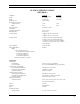
PRODUCT SPECIFICATION FOR CE MARKED EQUIPMENT
The MASTR
®
III Base Station and Auxiliary Receiver conform to the following Product Specifications.
EUROPEAN STANDARDS:
Safety: EN60065 (220 VAC applications only)
EMC: prETS 300 279 (August 1995)
TTD: Not Applicable
SUPPLEMENTARY INFORMATION:
The MASTR III Base Station and Auxiliary Receiver may be used in both trunked and conventional applications. Neither the
MASTR III Base Station nor the Auxiliary Receiver may be connected to leased lines in Europe without an additional line-
barrier protection device.