
Sizing Guide
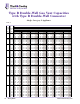
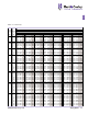
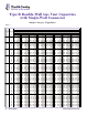

How to Use Single-Appliance Vent Tables
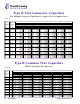
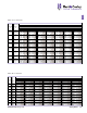
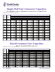
To determine the proper vent size for a single-appliance
vent, use Table 1 or 2 (pages 10-12).
• Determine Total Height (H) and Total Lateral Length
(L) based on location of appliance and vent and the
height to vent termination.
• Read down the Total Height (H) column at the left to
a height equal to the Total Height.
• Select the horizontal row for the appropriate Length
of Lateral (L) (zero for straight vertical vents).
• Read across to the column that represents the
appliance type and shows a capacity equal to or
greater than the appliance nameplate input for draft-
hood-equipped appliances or that falls between the
FAN Min and Max for FAN-assisted appliances.
• If the vent size shown at the top of the column
containing the correct capacity is equal to or larger
than the appliance draft hood, use the vent size
shown by the Table.
• If the vent shown is smaller than the draft hood size,
see Draft Hood to Vent Reduction on page 9.
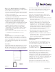
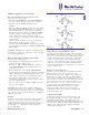
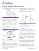
Example
A typical example of use of the Tables for Single-
Appliance Venting is shown in Figure 5. The furnace
has an input rating of 80,000 BTU per hour and is fan-
assisted. Total Height (H) of the vent is 30 feet with a
10- foot Total Lateral Length (L). The entire system is
Type B gas vent.
Procedure
Go down Vent Height (H) column of Table 1 to 30-foot
height with a 10-foot lateral under the FAN Min and
FAN Max column giving 37,000 and 150,000 BTUH for
a 4-inch vent. Generally, the smallest diameter that
will do the job is preferred. Note that if this system
were to have a single-wall connector, Table 2 would
have to be used. However, there is no solution!
Draft Hood to Vent Reduction
If the vent size determined from the Tables is less
than the size of a draft hood outlet or flue collar, the
smaller vent may be used, provided:
a) The vent is at least 10 feet high. When a vent is less
than 10 feet high, the vent should be at least as large
as the flue collar outlet.
b) Vents for draft hoods or flue collars 12 inches in
diameter or less should NOT be reduced more than
one pipe size. A 6- to 5-inch or a 12- to 10-inch
reduction is a one- pipe size reduction. For larger gas-
burning equipment, such as boilers having draft hood
sizes from 14 to 24 inches in diameter, reductions of
more than two pipe sizes are NOT recommended
(24- to 20-inch is a two-size reduction).
c) The maximum capacity listed in the tables for a fan-
assisted appliance is reduced by 10 percent.
d) Regardless of the size vent shown by the Tables for
such appliances, DO NOT connect any 4-inch draft
hoods to 3-inch vents. This provision does not
apply to fan-assisted appliances.
Additional Guidelines for Single-Appliance
Vent Systems
The flow area of the vertical vent shall not exceed
seven times the flow area of the appliance flue collar
area or the draft hood outlet area. For instance, if:
The flue collar diameter is: 3" 4" 5" 6" 7" 8"
The maximum common
vent diameter allowed is: 8" 10" 12" 14" 18" 20"
Single-appliance vent configurations with zero (0)
lateral lengths in Tables 1 and 2 have no elbows in the
system. For all other vent configurations with
indicated lateral lengths, the vent table capacities
include two 90° elbows. For each additional 90° fitting
or equivalent, the maximum capacity listed shall be
reduced by 10%. Two 45° elbows are equivalent to one
90° elbow. Two 90° elbows connected together are
equivalent to three in the system.
Interpolation is permitted between table entries.
Extrapolation beyond table entries is not permitted.
1
Figure 5
80,000 BTUH
FAN-ASSISTED
FURNACE
10 FT.
30 FT.
www.hartandcooley.com Sizing Guide 9