
Install Instructions

2
Model TLC - Firestop/Joist Shield, Pitched Ceiling Plate Installation Instructions
Hart & Cooley, Inc.
THE FUNCTION OF FIRESTOPPING
The purpose of firestopping in a chimney system is to
prevent or delay the rapid spread of fire (regardless of
the cause) in a home or building. Properly installed, the
sheet metal firestop prevents the chimney passageway
from becoming an easy pathway for fire to spread from
one floor to another.
PITCHED CEILING PLATE
(used at ceiling of equipment room only)
This part provides for firestopping and a finished
appearance for the ceiling opening when the chimney is
extended down into the equipment room to a freestanding
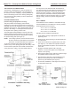
appliance (see Figure 3). Use a pitched ceiling plate for
pitched or flat ceilings. A firestop/joist shield is used on
the top side of the opening in either case.
The firestop/joist shield (installed on the top side of the
framed opening) requires trimming of the portion of the
shield that extends beneath the ceiling before installing
the pitched ceiling plate (see Figure 3).
NOTE: If the ceiling is pitched, a level frame will need to
be built to ensure the joist shield can be installed
level and in a vertical orientation (see Figure 3).
To trim the joist shield, after setting the joist shield in
position on top of the opening (with open end down), mark
a line around the perimeter of the shield at the elevation
of the plane of the ceiling. Use sheet metal shears to
trim the portion of the shield beneath the marked line.
The shield should now extend down through the framed
opening in the ceiling and end flush with the ceiling
surface as shown in Figure 3. After extending the pipe
down through the joist shield, install the pitched ceiling
plate by sliding it up around the pipe until it is in contact
with the ceiling. Secure the pitched ceiling plate with
screws.
WALL THIMBLE
A wall thimble must be installed in combustible through-
the-wall installations of the Model TLC chimney systems.
Framing dimensions are as follows.
16
1
/8” x 16
1
/8” for 10” diameter
18
1
/8” x 18
1
/8” for 12” diameter
20
1
/8” x 20
1
/8” for 14” diameter
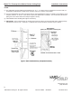
Following are the installation requirements.
1. Verify thimble opening is appropriate for diameter of
pipe being used.
2. Frame a level, square opening to the appropriate size
as noted above.
3. Insert the two halves from opposite sides of the wall
(see Figure 4). The half that incorporates the black
and/or round painted face plate is for the interior side
of the wall.
4. Engage the shields together until a snug fit is
achieved. Level the face plates of the thimble with
respect to the opening.
5. Attach the face plates to the wall using screws through
the predrilled holes found at each corner.
6. Seal around the perimeter of the wall thimble’s face
plate (on exterior side) with a silicone sealant to
prevent any rain infiltration (see Figure 5).
7. Proceed with installation of wall support and chimney
as described in Sheet S5.