
Install Instructions

5
Hart & Cooley, Inc.
Installation Instructions Model TLC All-Fuel Chimney
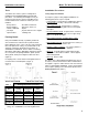
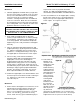
For proper installation, the attic opening must be fully
framed at 2 inches of clearance to the chimney pipe with
framing material of the same dimension as the ceiling
joists, per Table 2 (Framing Dimensions for Attic
Insulation Shield). The tabs on the plate of the attic
insulation shield are inserted in the framed opening
around the chimney. Nail the attic insulation shield base
to the framing dimensions with at least two per side, using
2d 1" spiral nails or 1" x #8 wood screws.
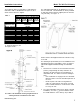
When an attic insulation shield is required above the
ceiling support into an attic as shown in Figure 4, ensure
that the base of the shield is flush with the top of the joist
framing, and nail in place. The telescoping portion of the
attic insulation shield will eliminate the need to trim the
bottom, when installed immediately above the ceiling
support. When fully extended, the attic insulation shield
will provide joist shielding when installed in a two-story
main floor application (Figure 6).
If insulation is blown in and adheres to the chimney pipe,
it must be brushed off to eliminate any possible contact of
this material with the chimney surface.
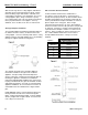
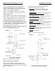
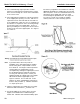
Firestop Radiation Shield Installation
A firestop radiation shield must be installed where the
chimney passes from one living space to another living
space, as shown in Figure 7. It is designed to provide
proper firestopping between floors and to keep direct
radiation from the chimney away from the joist framing.
Install the firestop radiation shield from below the joist
framing, and nail in place using 1" spiral nails. Ensure no
insulation is within the 2-inch airspace clearance around
the chimney. This includes the airspaces between the
firestop radiation shield and the joist framing.
When the chimney is enclosed in the attic area, a firestop
radiation shield must be installed at the ceiling level. If
the base of the firestop radiation shield does not fit flush
with the ceiling frame, measure the distance that the base
is sitting below the framing, and trim that amount off the
top of the firestop radiation shield before securing into
place.
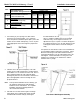
Elbow Installation
Two elbows may be used in an interior installation to
provide an offset, in order to avoid cutting of joists and to
clear other obstructions. Each elbow support will support
15 feet of chimney, and the maximum length of chimney
allowed between elbows is 6 feet. Forty-five-degree
(45°) elbows may be used only with oil or gas
appliances. See Chart 1 - Offset Chimney Installation
on page 16 of these instructions for details.
The female end of the elbows are not
embossed; this
ensures that proper alignment of the chimney system is
maintained. Locking bands must be installed at all
chimney joints, forming an offset.
Install the insulated offset elbow on the vertical chimney
length, and position the elbow in the required direction.
Fasten the elbow to the chimney length with the supplied
locking band.