
Instructions / Assembly


INSTALLATION
Carefully unpack the pump. Choose a location for its installation keeping in mind that the pump must be level and its inlet
must be below the lowest drain, either coil or furnace. Remove and discard the tagged shipping screw that is located on the
end of the switch cover box. This releases
the float for fully automatic operation.
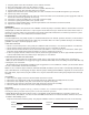
PIPING—Run flexible tubing or pipe from
the evaporator and furnace to the pump.
Insert the pipe into the drain inlet hole.
Make sure the pipe does not interfere with
the float. Cut an angle on the inlet pipe so
that it doesn’t close off against the bottom
of the pump. See Figure 1 – exploded
detail.
Connect 3/8” NPT piping to the discharge
port. Extend this piping or tubing straight
up as high as necessary. (Do not extend
this tubing past the head/GPH of the
pump installed). Do not kink the tubing,
as this will block the flow. From this
high point, slope the discharge tubing
downward to a point above the drain,
then turn down and extend to a point
below or level with the bottom of the
condensate pump. If it is not possible to
slope the discharge tubing downwards,
make an inverted “U” trap directly above
the pump at the highest point. (Figure 1)
A check valve is required and should be of a soft seat swing check design. A spring loaded ball check is permissible if the lift is
one half of the pump shut off level and the spring pressure is equal to, or less than one (1) psi.
ELECTRICAL CONNECTIONS— Review precautions on previous page before proceeding!
LINE VOLTAGE—Connect only to a source of constant power, not an intermittent source such as a fan or limit control circuit.
Connect the black and white wires to the appropriate voltage source and the green wire to ground.
The A2-X-1965 is equipped with a LOW VOLTAGE—AUXILIARY SAFETY SWITCH–Connect
the leads of the auxiliary safety switch to the thermostat control circuit of the air
conditioner/furnace. This will disrupt the thermostat demand in a high water condition.
(Figure 2)
CAUTION –Thermostat demand disruption should not be utilized if cooling or heating
requirements are a necessity. An alarm system should be used with the auxiliary switch
instead.
A2-X-1965 WIRING FOR DUAL VOLTAGE—The A2-X-1965 Dual Voltage Condensate pump
is wired for 115 volts from the manufacturer. NOTE: read entire procedure
before starting.
To connect to 115 VAC power supply, wire as follows.
1. Remove the top switch cover plate.
2. Install a proper conduit fitting thru the side hole of the main switch cover
and feed the power supply wires and thermostat control leads (optional)
into the housing.
3. Connect the orange and white wire to the power supply lines.
4. Connect the green (ground) wire to the ground supplied.
5. Connect the yellow auxiliary wires as previously described to the thermostat
control circuit leads.
6. Replace the top switch cover plate.
To connect to 230 VAC power supply , wire as follows. (Figure 3)
1. Remove the entire switch cover.
2. Remove the blue/yellow motor wire connector from the switch.
3. Cut the female connector from the blue/yellow motor wires.
4. Cut the wire connector from the black/red motor wires.