
Datasheet


01
.
31
II
I
IV
III
V
I
II
III
IV
V
III
I
II
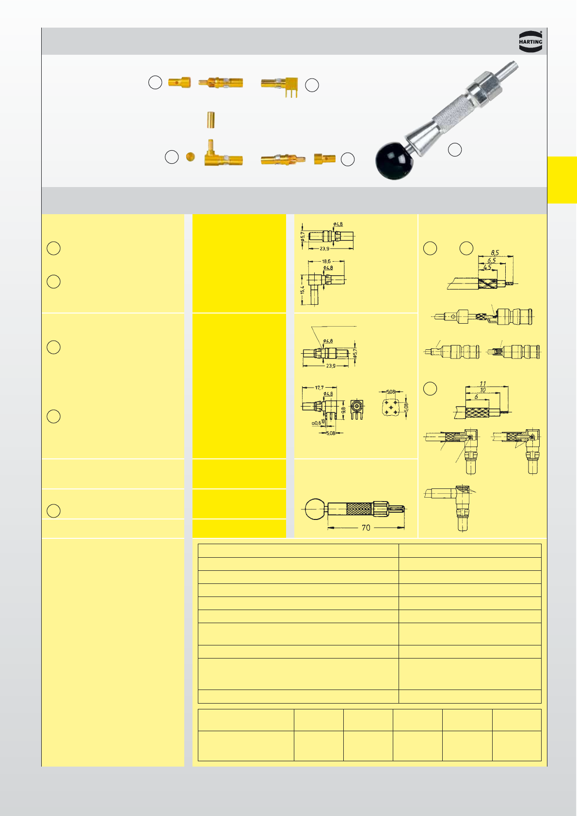
Types
signal to 2 A
DIN 41 612 · Special contacts type M
Part No.
Identification Performance level 2 Drawing Dimensions in mm
Male coaxial contacts
for female connectors
for straight solder 09 03 000 6160
and/or crimp termination *09 03 000 6181*
for angled solder 09 03 000 6161
and/or crimp termination
Female coaxial contacts
for male connectors
for straight solder without knurled area
and/or crimp termination 09 03 000 6260
*09 03 000 6281*
with knurled area
09 03 000 6274
angled for pcb termination 09 03 000 6262
*09 03 000 6269*
Crimping tool
for coaxial contacts 09 99 000 0194
Removal tool incl. removal jacket
for contact replacement 09 99 000 0174
Replacement removal jacket 09 99 000 0243
Electrical characteristics
of 50 Ω coaxial contacts
and wires
* Coaxial contact 75 Ω
Fibre optic contacts on request
Coaxial contacts
Cable group 2 Shell Screening Dielectric Internal wire
Hexagonal crimp
flexible wires øøøø
Spanner width
RG 174 A/U 2.5 2.0 1.5 0.48 3.25
RG 188 A/U 2.6 2.0 1.5 0.54 3.25
RG 316 U 2.5 2.0 1.5 0.54 3.25
Impedance 50 Ω
Max. working frequency 2 up to 10 GHz
VSWR-value 1.07 + 0.02 f [GHz]
Proof voltage 750 V / 50 Hz
Working voltage 250 V / 50 Hz
Insulation resistance ≥ 1 GΩ
Contact resistance – Center contact 10 mΩ
– Outer contact 3 mΩ
Contact current max. 1.5 A
Admissible power (depends on: frequency, Data on request
application, VSWR, environmental
characteristics)
75 Ohm versions Data on request
Assembly instruction
for contacts
and
1)
Solder pins for
hole ø 1 ± 0.1 mm
with/without
knurled area
Mound-insulator, solder,
cap, press together
crimp
crimp
solder
solder
solder
solder
for contacts