
Datasheet


01
.
34
64 09 73 164 7902 09 73 164 6902 09 73 164 2902
32 09 73 132 7902 09 73 132 6902 09 73 132 2902
96 09 73 196 7902 09 73 196 6902 09 73 196 2902
94 + 2
I
09 73 196 7952 09 73 196 6952 09 73 196 2952
64 09 73 164 7903 09 73 164 6903 09 73 164 2903
32 09 73 132 7903 09 73 132 6903 09 73 132 2903
96 09 73 196 7903 09 73 196 6903 09 73 196 2903
94 + 2
I
09 73 196 7953 09 73 196 6953 09 73 196 2953
64 09 73 164 7907 09 73 164 6907 09 73 164 2907
32 09 73 132 7907 09 73 132 6907 09 73 132 2907
96 09 73 196 7907 09 73 196 6907 09 73 196 2907
94 + 2
I
09 73 196 7957 09 73 196 6957 09 73 196 2957
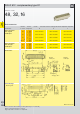
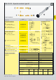
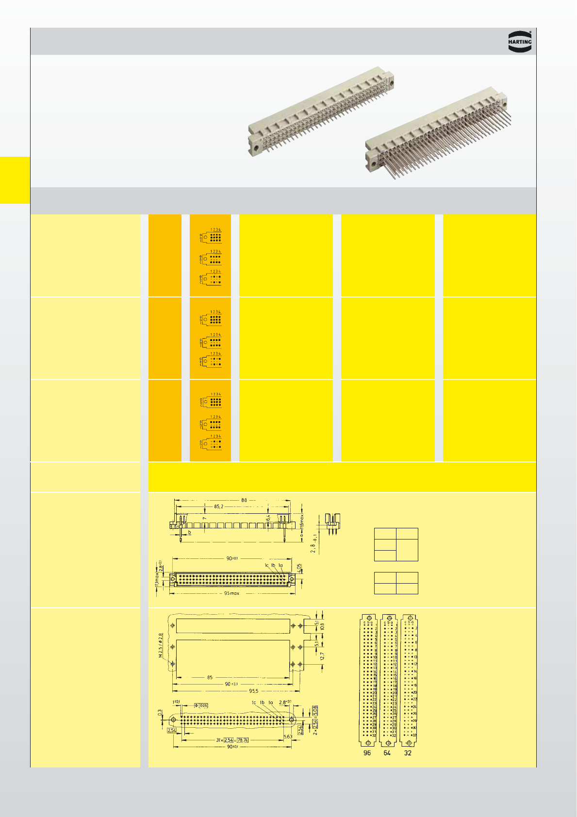
Types
signal to 2 A
DIN 41 612 · Type R
Male connectors
Number of contacts
96, 64, 32
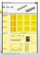
Number Contact
Identification
of contacts arrangement
Part No. Performance levels according to DIN 41 612. Explanation chapter 00
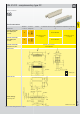
321
Male connector
with solder pins
2.5 mm
Male connector
with solder pins
4.0 mm
Male connector
with wrap posts
13 mm
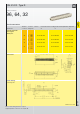
Dimensions
Panel cut out
Board drillings
Mounting side
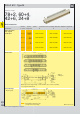
I
Male connectors with 2 leading contacts [(0.8 mm) pos. a1 and a32]
Other contact arrangements as well with lagging pins on request
Dimensions in mm
Part Nos. and variants
see chapter 04
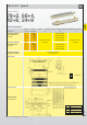
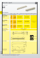
Male connector
with press-in pins
ab
2.5
4.0
ø0.7
ab
13
l 0.6
Solder pins
Wrap posts
Contact arrangement
View from termination side