
Datasheet


02
.
10
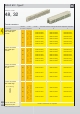
Types
signal to 6 A
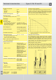
Technical characteristics Types D and E
Current carrying capacity
The current carrying capacity is limited by maximum temperature of
materials for inserts and contacts including terminals. The current
capacity curve is valid for continuous, non interrupted current loaded
contacts of connectors when simultaneous power on all contacts is
given, without exceeding the maximum temperature.
Control and test procedures according to DIN IEC 60 512
Fitting the crimp contacts
After crimping the wires onto the contacts with the help of a crimping
tool or an automatic crimping machine the contacts should be
correctly oriented and inserted into the cavities of the connector
moulding in the required configuration. They snap into position and
are firmly held in place. A light pull on the wire assures the correct
tensile strength of the contact. When using stranded wires with a
gauge below 0.37 mm² an insertion tool is necessary.
Removing the crimp contacts
The removal tool is inserted into a slot on the side of the respective
crimp cavity. This action compresses the contact retaining spring
therefore the contact can then be easily withdrawn using a light pull
on the wire. This action will cause no damage to the contact/wire
which can be repositioned/refitted as necessary. The drawing
demonstrates the crimp removal procedure (max. 5x).
Number of contacts
Type D 32
Type E 48
Contact spacing (mm)
Type D 5,08
Type E male connector 5.08 x 5.08
male connector 2.54 x 5.08
female connector 5.08 x 5.08
Working current
6 A max.
see current carrying capacity chart
Clearance
Types D und E ≥ 3.0 mm
Type E male connector ≥ 1.6 mm
row separation 2.54 mm
Creepage ≥ 3.0 mm
Working voltage
The working voltage also depends
according to the safety
on
the clearance and creepage
regulations of the equipment
dimensions
of the pcb itself and
Explanations see chapter 00
the associated wiring
Test voltage U
r.m.s.
1.55 kV
Contact resistance ≤ 15 mΩ for wire wrap and
solder connections
≤ 20 mΩ
including crimp connections
Insulation resistance ≥ 10
12
Ω
Temperature range
– 55 °C … + 125 °C
The higher temperature limit
includes the local ambient and
heating effects of the contacts
under load
Degree of protection for crimp terminal
IP 20
according to DIN 40 050
Electrical termination
Male connector
Solder pins for pcb
connections Ø 1.0 ± 0.1 mm
according to IEC 60 326-3
Female connector Wrap posts 1 x 1 mm
diagonal 1.34-1.45 mm
Solder pins for pcb
connections Ø 1.0 ± 0.1 mm
according to IEC 60 326-3
Angled solder pins 1 x 1 mm
for pcb connections
Ø 1.6 ± 0.1 mm
Solder lugs
Crimp terminal 0.09-1.5 mm²
Insertion and withdrawal force
32 way ≤ 40 N
48 way ≤ 75 N
Materials
Mouldings Thermoplastic resin,
glass-fibre filled, UL 94-V0
Contacts Copper alloy
Contact surface Contact zone: selectively
gold plated according to
performance level
1)
Termination zone: tinned
1)
Explanation of performance levels see chapter 00
Mating conditions see chapter 00
Coding systems see page 02.36
Mounting clips see chapter 00
Working current
Ambient temperature
Removal tool