M45, M60, M80 M45E, M60E, M80E, M90E Instructions for Installation and Use of Electric Sauna Heater Gebrauchs- und Montageanleitung des Elektrosaunaofens M (Sound) M 28022011 M M-E (Sound) M-E
EN DE These instructions for installation and use are intended for the owner or the person in charge of the sauna, as well as for the electrician in charge of the electrical installation of the heater. After completing the installation, the person in charge of the installation should give these instructions to the owner of the sauna or to the person in charge of its operation. Please read the instructions for use carefully before using the heater.
EN DE 1. INSTRUCTIONS FOR USE 1. BEDIENUNGSANLEITUNG 1.1. Piling of the Sauna Stones 1.1. Aufschichten der Saunaofensteine Important information on sauna stones: • The stones should be 5–10 cm in diameter. • Use solely angular split-face sauna stones that are intended for use in a heater. Peridotite, olivine-dolerite and olivine are suitable stone types. • Neither light, porous ceramic “stones“ nor soft soapstones should be used in the heater. They do not absorb enough heat when warmed up.
EN DE 1.2. Heating of the Sauna 1.2. Erhitzen der Saunakabine When operating the heater for the first time, both the heater and the stones emit smell. To remove the smell, the sauna room needs to be efficiently ventilated. If the heater output is suitable for the sauna room, it will take about an hour for a properly insulated sauna to reach the required bathing temperature ( 2.3.). The sauna stones normally reach the bathing temperature at the same time as the sauna room.
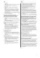
EN DE 1.3.3. Heater Off The heater switches off, when the timer turns the switch back to zero. You can switch the heater off at any time by turning the timer switch to zero yourself. Switch the heater off after bathing. Sometimes it may be advisable to leave the heater on for a while to let the wooden parts of the sauna dry properly. NOTE! Always check that the heater has switched off and stopped heating after the timer has turned the switch to zero. 1.3.3.
EN DE 1.5. Instructions for Bathing 1.5. Anleitungen zum Saunen • • • • • • • • • Begin by washing yourself. Stay in the sauna for as long as you feel comfortable. Forget all your troubles and relax. According to established sauna conventions, you must not disturb other bathers by speaking in a loud voice. Do not force other bathers from the sauna by throwing excessive amounts of water on the stones. Cool your skin down as necessary.
EN • • • • • condition. Check that all heating elements glow when the heater is on. Turn the thermostat to a higher setting ( 1.3.4.). Check that the heater output is sufficient ( 2.3.). Check the sauna stones ( 1.1.). Too tightly piled stones, the settling of stones with time or wrong stone type can hinder the air flow through the heater, which results in reduced heating efficiency. Check that the sauna room ventilation has been arranged correctly ( 2.2.).
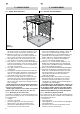
EN DE 2. SAUNA ROOM 2. SAUNAKABINE 2.1. Sauna Room Structure 2.1. Struktur der Saunakabine A F E D B A G C Figure 4. Abbildung 4. A. Insulation wool, thickness 50–100 mm. The sauna room must be insulated carefully so that the heater output can be kept moderately low. B. Moisture protection, e.g. aluminium paper. Place the glossy side of the paper towards the sauna. Tape the seams with aluminium tape. C. Vent gap of about 10 mm between the moisture protection and panel (recommendation). D.
EN DE 2.2. Sauna Room Ventilation 2.2. Belüftung der Saunakabine The air in the sauna room should change six times per hour. Figure 5 illustrates different sauna room ventilation options. D min. 1000 mm 180° min. 500 mm min. 500 mm 360° Die Saunaluft sollte sechsmal pro Stunde ausgetauscht werden. Abb. 5 zeigt verschiedene Optionen der Saunabelüftung. B Figure 5. Abbildung 5. A. Supply air vent location. If mechanical exhaust ventilation is used, place the supply air vent above the heater.
EN DE 3. INSTRUCTIONS FOR INSTALLATION 3.1. Before Installation Before installing the heater, study the instructions for installation. Check the following points: • Is the output and type of the heater suitable for the sauna room? The cubic volumes given in table 2 should be followed. • Is the supply voltage suitable for the heater? • The location of the heater fulfils the minimum requirements concerning safety distances given in fig. 6 and table 2.
EN DE 3.1.1. Change from right-handed to left-handed or vice versa (M) The controls of the heater (timer and thermostat) can be installed at either end of the connection box. If the controls have to be moved to the other end of the connection box, the end-pieces of the connection box must be exchanged with each other. 3.1.1. Wechsel der Anschlußrichtung (M) Die Steuergeräte der Sauna (Uhr und Thermostat) können an einem der beiden Enden der Anschlußgehäuse angebracht werden.
EN DE 3.1.2. Connecting the connecting cable to the heater It is simplest to connect the heater connecting cable while the heater is loose. 1. Turn the heater on its side so that the end with the controls is upwards. 2. Open the fixing screw at the control end about 10–12 mm out of the bottom of the electrical box and carefully pull the end-piece from the electrical box. 3.
EN DE 3.3. Electrical Connections 3.3. Elektroanschlüsse The heater may only be connected to the electrical network in accordance with the current regulations by an authorised, professional electrician. • The heater is semi-stationarily connected to the junction box (figure 10: 3) on the sauna wall. The junction box must be splash-proof, and its maximum height from the floor must not exceed 500 mm. • The connecting cable (figure 10: 4) must be of rubber cable type H07RN-F or its equivalent.
EN DE heater. It should be installed on the lateral centre line of the heater, 100 mm downwards from the ceiling. Figure 6. Do not place the supply air vent so that the air flow cools the temperature sensor. Figure 5. wand oberhalb des Saunaofens, 100 mm unterhalb der Decke auf der Achse in Breitenrichtung des Saunaofens angefracht. Abbildung 6. Luftzufuhr nicht so anbringen, dass sie den Temperaturfühler abkühlt. Abbildung 5. 3.5. Resetting the Overheat Protector 3.5.
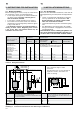
EN DE 1 2 3 CONTROL OF HEATING STEUERUNG DES ERHITZENS N L1 L2 L3 400 V 3N~ Figure 13. Electrical connections of M-E heater Abbildung 13. Elektroanschlüsse des Saunaofens M-E YELLOW/GELB RED/ROT WHITE/WEIß BLUE/BLAU 4 x 0.25 mm2 RESIDUAL CURRENT DEVICE FEHLERSTROMSCHUTZSCHALTER SENSOR FÜHLER LIGHT LICHT max. 100 W POWER SUPPLY HAUPTZENTRALE CONTROL OF HEATING OPTIONALE STEUERUNG FÜR ZUSATZHEIZUNG 3 x 1.5 mm2 (SSJ) RESIDUAL CURRENT DEVICE FEHLERSTROMSCHUTZSCHALTER LIGHT LICHT max.
EN NO ELECTRICAL CONNECTIONS ELECTRICAL CONNECTIONS (NORWAY/BELGIUM) (NORWAY/BELGIUM) Model Ovnsmodell Output Sauna room Effekt Badstu Cubic vol. Rommål Width/Bredd 41 cm (Sound 42 cm) Depth/Djup 29 cm (Sound 31 cm) Height/Höjd 65 cm (Sound 62 cm) Weight/vikt 16 kg Stones/Stenar max.
4. SPARE PARTS 4. ERSATZTEILE 10 1 2 3 4 9 8 6 7 5 1 2 3 4 5 6 7 8 9 10 Heating element Heating element Heating element Heating element Timer Thermostat End-piece of the Air flow spoiler Air flow spoiler Air flow spoiler 1500 2000 2670 3000 W/230 W/230 W/230 W/230 conn.