
Operation Manual


EN DE
11
3.1.1. Change from right-handed to left-handed or
vice versa (M)
The controls of the heater (timer and thermostat)
can be installed at either end of the connection box.
If the controls have to be moved to the other end of
the connection box, the end-pieces of the connection
box must be exchanged with each other.
3.1.1. Wechsel der Anschlußrichtung (M)
Die Steuergeräte der Sauna (Uhr und Thermostat)
können an einem der beiden Enden der Anschlußge-
häuse angebracht werden. Wenn die Steuergeräte an
das andere Ende der Elektrobuchse verlegt werden
müssen, werden die Stirnstücke der Elektrobuchse
untereinander vertauscht.
It is simplest to exchange the end-pieces before
fastening the heater to the wall.
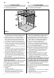
1. Turn the heater upside down so that the bot-
tom is upwards. Be careful not to cause dama-
ge to the steam distributor. Remove the end-
piece fastening screws (1 per end) from the
bottom of the connection box (see fig. 7).
2. Then, detach the end-piece with no switches.
After this, pull the end-piece with the timer
and thermostat carefully out of the connection
box. Special care must be taken when pulling
out the end-piece containing the timer and ther-
mostat, because the thermostat sensors and
wires linked with resistances are fastened to
the end-piece to be detached.
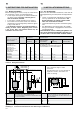
3. When both end-pieces have been detached, the
bottom of the connection box will open at its
joining point. Widen the opening with one hand
and carefully move the end-piece with its wires
to the other end of the connection box. Take
care not to hit the wires against the edges
of the connection box. Leave the end-piece
hanging from the wires and fasten the other
end-piece first. Press the joining seam at the
bottom of the electrical box together so that
the long holes match together, and the edge
of the back part of the box is on top. Turn the
fixing screw to its position. Prior to tightening
the screw, make sure that the edge of the con-
nection box is against the bottom of the groove
on the end-piece.
4. Place the end-piece with the timer and ther-
mostat into the box and fasten it loosely by a
screw (about 10–12 mm of the thread of the
screw should be visible). After connecting the
connecting cable (
3.1.2.), push the end-piece
into the electrical box and tighten the fixing
screw.
Am leichtesten ist es, den Wechsel der Stirnstücke
vor der Wandmontage durchzuführen.
1. Der Saunaofen wird umgedreht, so daß der Boden
nach oben zeigt. Beschädigen Sie nicht den Auf-
gußleiter. Die Befestigungsschrauben der Stirn-
stücke an der Unterseite der Anschlußgehäuse (1
Stk./Stirnseite) werden entfernt (siehe Abb. 7).
2. Danach wird zuerst das Stirnstück ohne Steuer-
funktionen entfernt. Dann wird das Stirnstück
mit dem Uhrschalter und dem Thermostat vor-
sichtig von der Anschlußgehäuse abgezogen.
Das Abziehen des Stirnstücks mit dem Uhr-
schalter und dem Thermostat muß mit beson-
derer Vorsicht erfolgen, da der Thermostatfüh-
ler und die Leitungen zu den Widerständen an
dem abzuziehenden Stirnstück befestigt sind.
3. Nach Entfemen der Stirnstücke läßt sich der
Boden der Anschlußgehäuse an der Fuge öff-
nen. Erweitern Sie die Öffnung mit der einen
Hand und ziehen Sie das Stirnstück mit den
Leitungen vorsichtig an das andere Ende der
Anschlußgehäuse. Achten Sie beim Verlegen
darauf, daß die Leitungen nicht durch die Ränder
der Öffnung in der Anschlußgehäuse beschädigt
werden. Das Stirnstück wird von den Leitungen
gehalten, während Sie zunächst das andere
Stirnstück befestigen. Drücken Sie den Verbin-
dungssaum am Boden der Anschlußgehäuse
fest, so daß die langen Öffnungen gegenüber
zu liegen kommen und der Rand der Buchsen-
rückseite zuoberst bleibt. Setzen Sie die Befe-
stigungsschraube ein. Stellen Sie vor Festziehen
der Schraube sicher, daß der Rand der Elektro-
buchse in der Nut des Stirnstücks liegt.
4. Das Stirnstück mit dem Uhrschalter und dem
Thermostat wird locker mit Schrauben (der Ge-
windeteil der Schraube bleibt zu ca. 10–12 mm
sichtbar) an der Buchse befestigt. Nach Befe-
stigung des Anschlußkabels (
3.1.2.) wird das
Stirnstück auf die Anschlußgehäuse geschoben
und die Befestigungsschraube angezogen.
Figure 7. Removal of the end-piece fastening screws
Abbildung 7. Lösen der Befestigungsschrauben der Stirnstücke