
Repair Guide, Diagrams and Assembling Charts
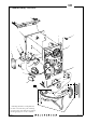
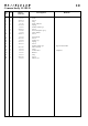
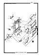
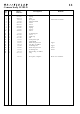
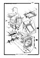
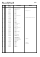
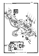

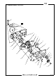
Table Of Contents
- Service Manual 555ELD Cover
- Contents list
- Related Service Infos
- 1. General description
- 2. Tools
- 3. Disassembly
- 4. Reassembly
- 5. Adjustment
- 6. Sub-assembly
- 7-25. Exploded Views and Spare Part lists
- 7. Shell
- 8. Motor housing
- 9. Right hand wall & main components
- 10. Left hand wall & electronics
- 11. Rear plate & auxiliary shutter
- 12. Front bayonet plate, mirror assembly & screen frame
- 13. Motor & electrical connections
- 14. Motor drive gear box
- 15. Shell 553ELX/500ELX
- 16. Motor housing 553ELX
- 17. Motor housing 500ELX
- 18. Right hand wall & main components 553ELX/500ELX
- 19. Left hand wall & electronics 553ELX/500ELX
- 20. Rear plate & auxiliary shutter 553ELX/500ELX
- 21. Front bayonet plate & screen frame 553ELX/500ELX
- 22. Motor & electrical connections 553ELX
- 23. Motor & electrical connections 500ELX
- 24. Motor drive gear box 553ELX/500ELX
- 25. IR Release unit

55510.EPS
990112
COPYRIGHT © 1999 ANDERS ENGSTRÖM
ANDERS ENGSTRÖM, ILLUSTRATÖR
Östra vägen 46
430 91 HÖNÖ
tel/fax 031-96 84 64
anders@aeillustr.se
10
May 1999
Camera body 555ELD
Revision 0
= Soldering should be accomplished in
less then 5 seconds. Keep the soldering
tip temperature less than 320ºC (608ºF).
Avoid applying force to the terminals.
1
2
3
4
5
6
7
8
9
10
11
12
10
13
14
15
16
17
18
20
21
22
23
19