Service Manual COPYRIGHT ' 2000 ANDERS ENGSTR M 903SWCOM.EPS ANDERS ENGSTR M, ILLUSTRAT R stra v gen 46 430 91 H N tel/fax 031- 96 84 64 anders.968464@telia.com 001027 January 2001 Victor Hasselblad AB Göteborg Sweden Copyright © 2001 by Victor Hasselblad AB. All rights reserved.
Contents list 903SWC 1. General description 2. Tools 3. Disassembly 4. Reassembly 5. Exploded view: Shell 6. Exploded view: Mechanism plate 7.
Related Service Infos 903SWC 12/96 Tripod foot adapter/kits 05/97 New tripod foot 20/97 New camera shell 04/01 New CD-ROM - Version 2.
1 903SWC General description Camera type: Mechanical wide-angle camera with a permanently attached 38 mm Biogon lens, and detachable optical viewfinder and optional interchangeable film magazines. Film format and film choices: 6x6 cm and 6x4.5 cm with different magazines; 120 and 220 with roll films, 70 mm perforated long rolls and Polaroid film with different magazines. Lens: Zeiss Biogon CF 4.5/38 mm T*.
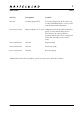
2 Tools 903SWC Tool No. Description Used for 902 894 Focusing gauge SWC Focus the Biogon lens in the same way as other Hasselblad lenses. Can be used with all horizontal collimators. 109950 0747 000 Biogon adapter for V-2223 Adaption between the shutter function gauge V-2223 and the Biogon lens. The shutter can consequently be repaired and the lens can be completed before the assembly to the camera body.
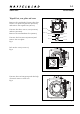
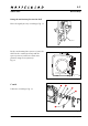
3:1 903SWC Disassembly Tripod Foot, rear plate and cone Remove the viewfinder. Unscrew the four screws, two (829790) and two (829760) and remove the tripod foot (30735). Unscrew the three screws, two (823783) and one (823780). Remove the intermediate foot (22821). 823640 22821 823780 823783 30735 Unscrew the four screws (823640) and remove the rear plate. Fig. 1 829790 829760 Fig. 1 90301.EPS 001026 Lift out the cone (13435-1). Fig. 2 13435-1 Fig. 2 90302.
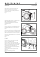
3:2 903SWC Disassembly Make sure the camera is released, then remove the release lever (13332-1). Unscrew the screw (822002) and remove the catch (21165). Fig. 4 21165 822002 820046 13332-1 The driving ring (21081-1) consists of two rings, mark their relative position. Unhook the spring (814707) from the washer (810928). Fig. 5 Fig. 4 90304.EPS 001026 "Mark" Unscrew the three screws (820046) to free the driving ring (21081-1) from the lens. Fig. 4 The camera body can now be lifted from the lens.
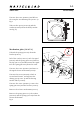
3:3 903SWC Disassembly Unscrew the screw (820047) and lift out the complete mechanism plate (30367-1). Fig. 7 30367-1 Take out the spacer (810721) and the washer (810928) from the shell (circular area fig. 8). 820047 Fig. 7 90307.EPS 001026 Mechanism plate (30367-1) 810721 13337 Unhook the spring (814705) from the bracket (12873). 822001 816709 810928 816751 12873 Lift of the catch (13427-1) incl. the signal (20737) and the spring (814705).
4:1 903SWC Reassembly Lubricate the camera as detailed in the appropriate lubrication chart. Use the lubricants listed below: = Isoflex Topas L32 = Isoflex PDP-48 = Loctite, e.g. Loctite 243 = Safety lacquer Mechanism plate (30367-1) Lubricate according to fig. 9. Attach the spring (816702), the washer (810542) and the spring (816751) to the release mechanism (13337). Fig. 9 90308.EPS 001026 Mount the release mechanism to the mechanism plate (30361-1) and place the two springs according to Fig. 10 A.
4:2 903SWC Reassembly Fitting the mechanism plate into the shell Place the signal (20737) according to fig. 11. 20737 Fig. 11 90310.EPS Fit the mechanism plate (30367-1) into the shell. Fit the washer (810928) and the spacer (810721) and secure them into position using screw (820047). Fig. 12 001023 30367-1 810928 810721 820047 Fig. 12 90307.EPS Crank 001026 Lubricate according to fig. 13. Fig. 13 Revision 0 90306.
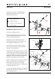
4:3 903SWC Reassembly Mount the housing (22323) on the camera body with the four screws (820015) and (820013). Check the axle so it turns freely. Put on the washer (810944) and the tooth wheel (22335). 820015 22335 823640 810944 Axle 22331 A 22328 Place the inner part of the crank (A) in the housing and secure it with the nylon string (22327). Mount the crank (22321) with the two screws (823640) and the spring (22328) secured with the two screws 821662). Fig.
4:4 903SWC Reassembly Check the release sequence: Cock the camera and move the outer driving ring slowly towards the release mechanism (13337). Free the release mechanism by hand and the shutter should release at a point just before the release mechanism leaves the nylon stop (13295). Fig. 17 13295 13337 90312.EPS Fig. 17 010130 If the shutter releases too early, or not at all, it is adjusted by changing the mesh between the gear (13320) and the toothed segment (13346).
4:5 903SWC Reassembly Re-install the rear lens group with the help of wrench 104117 0064 903. Fig. 20 Fig. 20 Install the cone (13435-1). Fig. 21 Fit the rear plate (22603). Secure with the four screws (823640). Check that the rear plate is aligned with the rear edge of the camera shell. If necessary adjust with washers. 90303.EPS 001026 13435-1 Fig. 21 90302.EPS 001026 Note! The rear plate must not protrude over the shell at any point. Fit the intermediate foot (22821).
COPYRIGHT ' 2000 ANDERS ENGSTR M 903SWC01.EPS ANDERS ENGSTR M, ILLUSTRAT R stra v gen 46 430 91 H N tel/fax 031- 96 84 64 anders.968464@telia.
5 903SWC Pos Pcs No. 1 Spare Part No.
5 903SWC Pos Pcs No. Spare Part No. Description Remark 54 55 56 57 58 1 2 1 1 1 22 997 830 435 13 435 -1 13 394 -1 20 769 -1 Magazine hook Screw Cone, complete Cone Frame 59 60 1 4 4 4 4 12 871 -1 810 549 810 542 810 543 810 545 Foam strip Washer Washer Washer Washer 0,10 mm 0,15 mm 0,20 mm 0,30 mm 61 62 4 1 823 640 22 603 Screw Rear plate Please state serial No.
6 COPYRIGHT ' 2000 ANDERS ENGSTR M 903SWC02.EPS ANDERS ENGSTR M, ILLUSTRAT R stra v gen 46 430 91 H N tel/fax 031- 96 84 64 anders.968464@telia.
6 903SWC Pos Pcs No. Description Spare Part No.
430 91 H N tel/fax 031- 96 84 64 anders.968464@telia.
7 Viewfinder SWC Pos Pcs No. Spare Part No.