
Instructions / Assembly
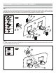
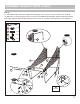
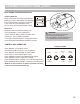
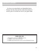
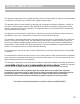

FIG. 11
15. Attach the Control Box (#16) to the middle of Tube 11 (#11) using two Bolts (#30) as shown in FIG.11A.
16. Run the rest of the Control Wire through the loops on the bottom side of the Ball Return Net (#35). Hold the Control
Wire on Tube 11 (#11) using the Self-Stick Straps (#34) as shown in FIG.11.
ASSEMBLY INSTRUCTIONS (CONT.)
13
Control Wire
X1
16
X2
30
X2
34
FIG.11
11
16
34
30
11
35
FIG. 12
14
Sensor Wire
Sensor Wire
Electronic Scorer
Control Wire
FIG. 12A
ON / OFF
CONTROL
WIRE /
CONTROL
CABLE
VISITOR
FIG. 12
17. Connect the Sensor Wire from Switch Sensor (#15) to the Electronic Scorer (#14) as shown in FIG.12.
Connect the Control Wire to the Electronic Scorer (#14) as shown in FIG.12 and 12A.
FIG.11A