ALLURE 48-IN FOOSBALL TABLE with TELESCOPIC SAFETY RODS ASSEMBLY INSTRUCTIONS Ver.
Thank you for purchasing this product. We work around the clock and around the globe to ensure that our products maintain the highest possible quality. However, in the rare case of issues during assembly or use of this product, please contact our Consumer Hotline at 800-759-0977 for immediate assistance before contacting your retailer. Please read the warranty information at the back of these assembly instructions for further details.
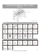
ALLURE 48-IN FOOSBALL TABLE - BG5015 Parts List P1 P9 P11 P2 P14 P17 P13 P3 P12 H7 P15 P10 P18,P19,P20 P2 P4 P4 P1 P7 P9 P8 P7 P8 P6 P8 P5 Illustrations Not to Scale PARTS P1 NGP7213 X2 P2 NGP7214 P3 NGP7215 X2 X1 END PANEL SIDE PANEL P4 NGP7216 P5 NGP7217 X2 X2 RIGHT LEG LEFT LEG P11 NGP55131 P12 NGP7220 PLAYFIELD P6 NGP7218 X2 P7 NGP7219 X2 SUPPORT BRACE P8 NGP50785 P9 NGP5507 P10 NGP5513 X4 LEG LEVELER X8 ROD HANDLE X8 X8 X2 X4 X2 ROD BUMPER ROD WASHER 4-
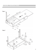
ASSEMBLY INSTRUCTIONS Step 1 P1 P3 P4 P1 P5 P2 H3 H2 H3 H1 Step 2 P5 P2 P4 P1 H3 P4 H1 P3 P5 H3 H2 P1 4
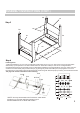
ASSEMBLY INSTRUCTIONS (CONT.) P5 P7 Step 3 H4 P8 P4 P7 P6 P3 H5 Step 4 Installing Rods* 1. Place Rod Washer (P11) over end of handle side of Player Rod (P12, P13, P14), then insert rod end into appropriate Side Panel (P1) hole (all same color team handles will be on same side of table) in order show on diagram below. 2. Insert Rod Insert (P15) into opposite end of rod while placing Washer (H7) and Rod Bumper (P10) onto insert as shown. 3.
ASSEMBLY INSTRUCTIONS (CONT.
180-DAY LIMITED WARRANTY This product is warranted to the original purchaser to be free from defects in material or workmanship for a period of 180 days from the date of the original retail purchase. This warranty does not cover defects or damage due to improper installation, alteration, accident or any other event beyond the control of the manufacturer. Defects or damage resulting from misuse, abuse or negligence will void this warranty.
TABLE DE SOCCER ALLURE 1,22 m AVEC TIGESDESÉCURITÉTELESCOPIQUES INSTRUCTIONS D’ASSEMBLAGE Ver.
MERCI! Merci d’avoir acheté notre produit. Nous travaillons 24 heures sur 24, partout dans le monde, à garantir que nos produits sont de la meilleure qualité possible. Toutefois, dans les rares cas de problèmes lors du montage ou de l'utilisation de ce produit, se il vous plaît communiquer avec notre service à la clientèle au 800-759-0977pour une aide immédiate avant de contacter votre revendeur.
TABLE DE SOCCER ALLURE 1,22 m - BG5015 Liste des pièces P1 P9 P11 P2 P14 P17 P13 P3 P12 H7 P15 P10 P18,P19,P20 P2 P4 P4 P1 P7 P9 P8 P7 P8 P6 P8 illustrations non à l'échelle P5 PIÈCES P1 NGP7213 P2 NGP7214 X2 P3 NGP7215 X2 X1 panneau d’extrémité panneau latéral P4 NGP7216 P9 NGP5507 P10 NGP5513 X4 patin de nivellement X8 X8 P15 NGP7223 poignée de tige butoir de tige P16 NGP5102 P17 NGP7224 X2 X2 X8 insert de tige joueurs balle de soccer marqueur manuel P6 NGP7218 p
INSTRUCTIONS D’ASSEMBLAGE étape 1 P1 P3 P4 P1 P5 P2 H3 H2 H3 H1 étape 2 P5 P2 P4 P1 H3 P4 H1 P3 P5 H3 H2 P1 4
INSTRUCTIONS D’ASSEMBLAGE (suite) P5 P7 étape 3 H4 P8 P4 P7 P6 P3 H5 étape 4 Installation de Rods * 1. Placer la rondelle (P11) sur l'extrémité de la poignée de cote du tige joueurs (P12, P13, P14), puis insérer l'extrémité de la tige dans le trou approprié du panneau latéral (P1) (toutes les poignées d'équipe de même couleur seront du même côté de la table) dans l'ordre montrent sur le diagramme ci-dessous. 2.
INSTRUCTIONS D’ASSEMBLAGE (suite) étape 5 P9 P11 P17 H6 H7 P10 P15 P19 P18 P1 P20 6
GARANTIE LIMITÉE DE 180 JOURS La garantie du produit est valide pour l'acheteur original en ce qui a trait aux pièces défectueuses ou à la main-d’œuvre pour une période de 180 jours de la date d’achat. Cette garantie n’est couvre pas les dommages causés par accident, par modification, par une installation défectueuse ou tout autre événement hors du contrôle du fabricant. Tout défaut ou dommage résultant de la négligence ou d’une mauvaise utilisation annule cette garantie.