USER MANUAL Series X - Maritime Multi Computer (MMC) Models HD 08T21 MMC-xxx-xxxx - 8.0 inch Maritime Multi Computer HD 13T21 MMC-xxx-xxxx - 13.3 inch Maritime Multi Computer User Manual MMC Series X Compact Updated: 03 Jun 2015 Doc Id: INB100485-2 (Rev 7) Created: 363 Approved: 6987/6784 Please visit www.hatteland-display.com for the latest electronic version of this manual. Hatteland Display AS, Stokkastrandvegen 87B, N-5578 Nedre Vats, Norway Tel: (+47) 4814 2200 - mail@hatteland-display.com - www.
Copyright © 2015 Hatteland Display AS Stokkastrandvegen 87B, N-5578 Nedre Vats, Norway. All rights are reserved by Hatteland Display AS. This information may not, in whole or in part, be copied, photocopied, reproduced, translated or reduced to any electronic medium or machinereadable form without the prior written consent of Hatteland Display AS. Review also: www.hatteland-display.com/pdf/misc/doc100703-1_permission_to_create_user_manuals.
Contents Contents........................................................................................... 3 Contents of package.....................................................................................................5 General............................................................................................. 7 About this manual.........................................................................................................8 About Hatteland Display............................
Contents Specifications................................................................................ 33 Specifications - HD 08T21 MMC-xxx-xxxx..................................................................34 Specifications - HD 13T21 MMC-xxx-xxxx..................................................................35 With Intel® Atom™ CPU......................................................................................... 35 Specifications - HD 13T21 MMC-xxx-xxxx.......................................
Contents of package Note: Entries listed below are for Standard factory shipments. Customized factory shipments may deviate from this list. Item MEDIA STD01 Description Documentation and Driver DVD for factory installed components like mainboard, IDE, network etc. It also includes the Touch Screen driver for units delivered with a factory mounted touch screen. For most recent drivers, please visit “www.hatteland-display.com/archive”.
This page left intentionally blank 6
General 7
Hatteland Display AS About this manual The manual contains electrical, mechanical and input/output signal specifications. All specifications in this manual, due to manufacturing, new revisions and approvals, are subject to change without notice. However, the last update and revision of this manual are shown both on the frontpage and also in the “Revision History” chapter at the end of the manual.
Compact Panel Computers Series X Maritime Multi Computer (MMC) - Introduction Series X Panel Computers offer the ultimate in performance, convenience, state of the art design and enduring quality for system integrators and boat builders. Series X products offer a range of feature sets optimized for varying requirements and applications.
Touch screen products Introduction to products with touch screen Nearly all of our Series X products with touch screen uses Projected Capacitive Touch screen (PCTS), widely used with great success on mobile phones and typical pad devices. PCTS can be equally effective also for marine applications. One of the advantages of PCTS is that it has features seen in both resistive and surface capacitive touch screen technologies.
Touch screen products Touch Screen Drivers and Documentation All units are shipped with a Documentation and Drivers DVD or CD which contains suitable drivers* for touch screens. (Named MEDIA STD01). You can also visit our website www.hatteland-display.com to view the same list (or even recently new added products) for our models with touch screen. Before using the touch screen, it should be calibrated for your system. Please install the 3rd party software* and use the Calibrate function.
Product Labeling Introduction This section details the locations, content details and specifications for factory mounted labels for all currently available standard Hatteland Display Panel Computer (MMC) models. This information will in most cases also apply for most Customized Models as well, but may differ based on customer requirements, in that case, please refer to the customized User Manual (paper or electronic version, dependent on customer requirements).
Product Labeling Label Locations Number ID and coloring based on “Label Size and Types“ table from previous page. All illustrations below is seen from rear (and side where needed) with connectors facing down. Actual labels regarding its size and text orientation vs product size is drawn in. Due to space restrictions on selected units, some labels will be rotated 90 degrees to fit properly.
Product Labeling Warranty Label If you are to perform service on a unit still under warranty, any warranty will be void if this label show signs of removal attempts (re-gluing) or removed completely. This label is located on the back of the product and covers a key screw. This is to aid service departments to determine if there has been any unauthorized service on a unit still under warranty.
Installation 15
General Installation Recommendations First Things First! ATTENTION! To prevent damage to chassis and glass, please review the illustrations below before handling units. CORRECT HANDLING ! WRONG HANDLING ! IND100148-5 - Rev 03 Humidity Exposure Notice! Applies for non-bonded product only.
General Installation Recommendations 7. If the push buttons of the product are not illuminated, an external, dimmable illumination (IEC 60945 Ed. 4, 4.2.2.3, e.g. Goose neck light) is required for navigational use. The illumination shall be dazzle-free and adjustable to extinction. 8. Information about necessary pull-relievers for cables is indicated in the Physical Connection section of this manual. Attention must be paid to this information so that cable breaks will not occur, e.g. during service work. 9.
General Installation Recommendations D: General rule for console mounted units: To ensure proper cooling airflow, long-life and stable operation for all units, please make sure that the console casing have either fans or decent ventilation holes to prevent overheating inside the console due to the combined temperature of both Display or Panel Computer units together with other electronic instruments.
General Installation Recommendations Ergonomics 1. The front surface of the display glass has an anti-reflective (AR) coating which can be scratched and damaged with improper cleaning. It is recommended to use only 90+% pure Isopropyl alcohol (Isopropanol) and a soft fabric cloth for this first cleaning. Fold a cloth into a small pad, dampen the cloth with alcohol, and wipe the glass from one edge to the other in one direction with one continuous motion. The product glass will require cleaning as needed.
General Installation Recommendations Maximum Cable Length Any cable should generally be kept as short as possible to provide a high quality input/output. The maximum signal cable length will depend on the signal resolution and frequency, but also on the quality of the signal output from the computer/radar.
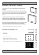
General Installation Recommendations Housing / Terminal Block Connector Overview Housing / Terminal Block connectors are available in different sizes (example 2-pin, 4-pin, 5-pin) which plugs into the connector area of the unit. They are mounted by factory default and delivered with the unit. The housing / terminal block connectors have steering rails, which ensures that it can not be mounted wrong. The color of these connectors may vary between black, green and orange depending on manufacturer.
General Installation Recommendations If your installation require additional cable fasteners support, please visit and purchase directly from manufacturer: Illustrations below are approximate, actual Housing and Hood may deviate slightly, but function remains the same. Phoenix Cable Housing - Illustration Weidmüller Cover Hood - Illustration Weidmüller 1005290000 - BCZ 3.81 AH04 BK BX (4-pin) Weidmüller 1005300000 - BCZ 3.
Physical Connections Terminal Label Markings of 8 inch unit 2 1 3 CAN I/O Module (optional) 1 2 3 Digital Output (optional) Connection area of 8 inch unit CAN I/O (optional) Digital Output / Input USB 1,2 Digital Output (optional) 2 x RJ45 Network Digital Output & Serial I/O Grounding Screw 2 x DC Power Inputs 23 IND100133-46
Physical Connections Terminal Label Markings of 13 inch unit (Intel® Atom™ CPU) 2 1 Digital Output (optional) 3 CAN I/O Module (optional) 1 2 3 Connection area of 13 inch unit (with Intel® Atom™ CPU) CAN I/O (optional) Digital Output / Input USB 1,2 2 x DC Power Inputs Digital Output (optional) 2 x RJ45 Network Digital Output & Serial I/O Grounding Screw 24 IND100133-46
Physical Connections Terminal Label Markings of 13 inch unit (Intel® Core™2 Duo CPU) 2 1 Digital Output (optional) 3 CAN I/O Module (optional) 1 2 3 Connection area of 13 inch unit (with Intel® Core™2 Duo CPU) CAN I/O (optional) Grounding Screw 4 x RJ45 Network Digital Output & Serial I/O USB 1,2,3,4 2 x DC Power Inputs Digital Output (optional) DVI-I Output Digital Output / Input 25 IND100133-46
Physical Connections Note: For connectivity, please review “Housing / Terminal Block Connector Overview“ and “Pinout Assignments” sections in this manual. For Application Programming Interface (API) usage and Detailed IO Specifications/Circuits, please review the appendix chapters in this manual. DIGITAL OUPUT (X1 DIG OUT) (Optional): This is a standard change over relay contact which can be programmed by the user application.
Physical Connections Network/LAN INPUT / OUTPUT (NET A / NET B / NET C / NET D): Supports 10/100/1000Mbps Ethernet (LAN). Suitable for twisted pair cables CAT.5E. Make sure the network cable connector ”clicks” into the RJ-45 connector. This connector will allow remote control of the display unit to control common functions like brightness, change input source and more. Based on model, 2 or 4 RJ-45 ports is available.
This page left intentionally blank 28
Operation MMC Products 29
User Controls USER CONTROLS OVERVIEW The units are designed by using Glass Display Control™ (GDC) touch technology to allow interactivity adjusting brilliance (brightness) and control power on / off with the use of illuminated symbols. Note that these symbols are only visible (backlight illuminated) when suitable power is connected.
User Controls Brightness Adjust: Brilliance / Brightness adjustment of the displayed image is adjusted by touching the (-) or (+) illuminated symbols. Both symbols are visible as long as the unit is powered (cable connected). These buttons has extended functionality. Additional Functionality for Brightness Adjust (-/+) and ON/OFF touch symbols via API Touch Detection of these symbols goes through the unit’s regular Touch Screen driver and can be accessed via API to allow extended functionality.
User Controls Buzzer: The location of the Buzzer is not visible for the eye. You can implement the Buzzer in your own applications and systems by using the dedicated API functionality (specifically DOC101014-1 and DOC101200-1 documents). For Application Programming Interface (API) usage, please review dedicated chapter in this manual.
Specifications 33
Specifications - HD 08T21 MMC-xxx-xxxx SPECIFICATIONS Note: All specifications are subject to change without prior notice! Please visit www.hatteland-display.com for the latest electronic version. All specifications are subject to change without prior notice! TFT Technology: Physical Dimensions: • 8.
Specifications - HD 13T21 MMC-xxx-xxxx SPECIFICATIONS Note: All specifications are subject to change without prior notice! Please visit www.hatteland-display.com for the latest electronic version. All specifications are subject to change without prior notice! TFT Technology: Physical Dimensions: • 13.
Specifications - HD 13T21 MMC-xxx-xxxx SPECIFICATIONS Note: All specifications are subject to change without prior notice! Please visit www.hatteland-display.com for the latest electronic version. All specifications are subject to change without prior notice! TFT Technology: Physical Dimensions: • 13.
Specifications Accessories 37
Specifications - JH C01MF A-A This information may not, in whole or in part, be copied, photocopied, reproduced, translated or reduced to any electronic medium or machinereadable form without the prior written consent of Hatteland Display AS. The products may not be copied or duplicated in any way.
Specifications - CAN Module with CO-Processor All specifications are subject to change without prior notice! DATA SHEET This information may not, in whole or in part, be copied, photocopied, reproduced, translated or reduced to any electronic medium or machinereadable form without the prior written consent of Hatteland Display AS. The products may not be copied or duplicated in any way.
Specifications - NMEA / IEC COM Module RS-422 / RS-485 DATA SHEET This information may not, in whole or in part, be copied, photocopied, reproduced, translated or reduced to any electronic medium or machinereadable form without the prior written consent of Hatteland Display AS. The products may not be copied or duplicated in any way.
Specifications - NMEA / IEC COM Module RS-422 / RS-485 NMEA RS-422 / RS-485 (ECDIS) module (PCA100293-1): Suitable for communication with serial protocol based equipment. Connect and secure your cables to the Terminal Block 3.81 connector. For more information please review the Data Sheet in the Appendix chapter as well as the “Housing Connector Overview” in this manual. Note: Our units is based on an isolated RS-485 interface with enhancements to meet NMEA standard.
Specifications - COM Module RS-232 All specifications are subject to change without prior notice! DATA SHEET This information may not, in whole or in part, be copied, photocopied, reproduced, translated or reduced to any electronic medium or machinereadable form without the prior written consent of Hatteland Display AS. The products may not be copied or duplicated in any way.
Specifications - External Modules (USB) All specifications are subject to change without prior notice! DATA SHEET This information may not, in whole or in part, be copied, photocopied, reproduced, translated or reduced to any electronic medium or machinereadable form without the prior written consent of Hatteland Display AS. The products may not be copied or duplicated in any way.
Specifications - External Modules (USB) All specifications are subject to change without prior notice! SPECIFICATIONS Note: All specifications are subject to change without prior notice! Please visit www.hatteland-display.com for the latest electronic version. Ordering Details: TypeNumber Description Internal Specications (link to separate datasheets) HT 00262 OPT-A1 NMEA COM 4 x NMEA RS-422/RS-485 isolated Via 5-pin Terminal Block 3.
This page left intentionally blank 45
Technical Drawings 46
This document is the property of Hatteland Display AS. This document and any authorized reproduction thereof, must not be used in any way against the interest of Hatteland Display AS. Any authorized reproduction, in whole or in part, must include this legend. Hatteland Display Proprietary information. Not to be distributed to any third party without written permission. Dimensions might be shown with or without decimals and indicated as mm [inches]. Tolerance on drawings is +/- 1mm.
This document is the property of Hatteland Display AS. This document and any authorized reproduction thereof, must not be used in any way against the interest of Hatteland Display AS. Any authorized reproduction, in whole or in part, must include this legend. Hatteland Display Proprietary information. Not to be distributed to any third party without written permission. Dimensions might be shown with or without decimals and indicated as mm [inches]. Tolerance on drawings is +/- 1mm.
This document is the property of Hatteland Display AS. This document and any authorized reproduction thereof, must not be used in any way against the interest of Hatteland Display AS. Any authorized reproduction, in whole or in part, must include this legend. Hatteland Display Proprietary information. Not to be distributed to any third party without written permission. Dimensions might be shown with or without decimals and indicated as mm [inches]. Tolerance on drawings is +/- 1mm.
Technical Drawings - Accessories 50
This document is the property of Hatteland Display AS. This document and any authorized reproduction thereof, must not be used in any way against the interest of Hatteland Display AS. Any authorized reproduction, in whole or in part, must include this legend. Hatteland Display Proprietary information. Not to be distributed to any third party without written permission. Dimensions might be shown with or without decimals and indicated as mm [inches]. Tolerance on drawings is +/- 1mm.
Appendixes 52
API / SMBUS / Touch Keypad Access Introduction API = Application programming interface. Standard industry term for how software components should interact. SMBUS = System Management Bus. Standard industry term on how to access hardware registers directly. Installing API Drivers In order to access and communicate with the HD 08T21 MMC and HD 13T21 MMC computer unit, it may or may not already have pre-installed drivers depending on factory defaults.
API / SMBUS / Touch Keypad Access Accessing API In order to access and communicate with the HD 08T21 MMC and HD 13T21 MMC computer units, please review the in-depth documents below (available on “Drivers and Documentation DVD” (MEDIA STD-008 or higher), as well as through our website www.hatteland-display.com, links below. DOC101014-1 - API_AIPC The API is created to make it easier for users to access the many functions available through software interaction.
API / SMBUS / Touch Keypad Access CAN Module Documentation Additional documentation is also available for accessing and controlling the CAN module available from Hatteland Display. Two different options are available with the same functionality. Internal Factory installed module: HT 00254 OPT-A1 External CAN Module USB: HT 00264 OPT-A1 References: http://www.hatteland-display.com/pdf/ind_ds/ds_ht00254opt-a1_can_module.pdf http://www.hatteland-display.com/accessory_ht00264opt-a1.
API / SMBUS / Touch Keypad Access Extended functionality for Brightness (-/+) and Power ON/OFF touch symbols As referenced in the “User Controls Overview” chapter in this manual, you can access and interpret actual touches detected on the 3 front symbols (Brightness and Power ON/OFF) through the Touch Screen driver installed for the unit via its HID interfacing protocol.
Detailed IO Specifications Introduction All DIO connectors illustrated below are intended to be used in control circuits and does therefore need external fuse to meet safety agency approvals. DIGITAL OUPUT (X1 DIG OUT): Relay Software Control Signals (API) K1 K1_EN K1_DIS Symbol with references to actual pin assignments (3 digits) X1 - Out: 011 (COM) Mechanical relay. No internal fuse. Rated current = 3A. Voltage = 0-265VAC, 0-32VDC.
Detailed IO Specifications DIGITAL OUTPUT (X1 DIG OUT): Note: Applies for 8/13 inch units with Intel® Core™2 Duo CPU. Brief explanation for X1 DIG OUT: HS and CPLD_HS1 signals, managed via software, controls the HS1 relay. In a closed state, the pin X1 - Out: 041 (OUT+) and pin X1 - Out: 042 (OUT1-) are shortened. HS and CPLD_HS2 signals, managed via software, controls the HS2 relay. In a closed state, the pin X1 - Out: 031 (COM) and Pin X1 - Out: 032 (NO) are shortened.
Detailed IO Specifications DIGITAL INPUT: (X1 DIG IN) Brief explanation for X1 DIG In: The DIO0_GPI4 signal can be read via software. It is normally high. If 12-24V is applied between pin X1 - In: 052 (+24 VDC) and pin X1 - In: 053 (GND), the DIO0_GPI4 signal will go to a low state. The DIO0_GPI5 signal can be read via software. It is normally low. If the pin X1 - In: 061 (+24 VDC) and pin X1 - In: 062 is shortened, the DIO0_GPI5 signal will go to a high state.
Detailed IO Specifications DIGITAL OUTPUT: (X1 DIG OUT): Relay Software Control Signals (API) Symbol with references to actual pin assignments (3 digits) K2/RELAY Intel® Atom™ Models: AIPC_K2_EN AIPC_K2_DIS X1 - Out: 021 (COM) Intel® Core™2 Duo Models: CPLD_RELAY_EN CPLD_RELAY_DIS X1 - Out: 022 (NC) Mechanical relay. No internal fuse. Current = 3A. Voltage = 0-265VAC, 0-32VDC.
SSD Selection Guide Solid State Disk (SSD) Devices Last revised : 4 November 2014 SSD's has many benefits over conventional hard drives, but when it comes to write endurance it is important to choose the technology to be used with care. It is of very high importance to consider several aspects when using an SSD for a particular application, below the most critical ones, such as: - Nature of the application, data written to disk during a defined time period (worst case).
SSD Selection Guide Calculation of required size of SSD (Multi-Level Cell - MLC) device) The table below details the write endurance of the an enterprise environment. All values are verified by Hatteland Display during the qualification / selection process. Write Endurance Specifications Intel® SSD 320 Series Write Endurance Specifications Current 2.
SSD Selection Guide Example (based on Intel® SSD 320 Series) A general assessment based on requirements to determine the most suitable SSD device. When these factors are known or specified in detail, we can calculate and conclude which SSD device is most suitable (see bottom of page). Question Client Answer We need to know how much data is written to disk Chart Data : 2GB /Week (worst case) during a known time period (per second, Log/User Data: : 10kB /Sec minute, hour etc.
SSD Selection Guide Preparation 1: Install "Intel® Solid-Sate Drive Toolbox" at target system. 2: Install the unit in valid configuration, i.e. the application shall running valid use case, if possible use worst case scenario (with respect to disk activity). 3: Before start of measurement, check and store actual SMART data. - Start "Intel® Solid-Sate Drive toolbol". - Refresh (button at home screen). - Export SMART data, store current data at file (button at home screen).
Pinout Assignments Connectors illustrated here are either standard by factory default or may be available (through factory customization). Note that some combinations may not be possible due to space restrictions. List also valid for customized models. All pin out assignments are seen from users Point of View (POV) while looking straight at the connector. Please review the dedicated datasheet or technical drawings for your actual unit to identify and determine the presence of desired connector.
Pinout Assignments 10-pin Digital Output / Input & Serial Module “Mechanical Relay & COM (isolated RS-422/485)” 5-pin Digital Output Module “Safety Signal Relay” X1 DIG OUT X1 DIG OUT 1 2 3 4 5 1 2 3 4 5 X7 SER I/O 1 3 4 5 COM (Common Center Terminal) Not Connected X1 - N/C Not in use X1 - Out: 014 NO (Normally Open) Not Connected X1 - N/C Not in use X1 - Out: 012 NC (Normally Closed) PIN 01 X1 - Out: 011 PIN 01 X1 - Out: 021 PIN 02 PIN 02 PIN 03 PIN 04 PIN 05 COM (Common Center Terminal) X1 -
Basic Trouble-shooting GENERAL ISSUES FOR TFT PANEL BASED PRODUCTS Note: Applies for a range of various products. This is only meant as a general guide. NO PICTURE / LED BEHAVIOUR: If there is no light at all in the LED at the FRONT, check power cables. If the LED in front is green then check if the brightness is set/adjusted to max brightness. Lack of image is most likely to be caused by incorrect connection, lack of power or wrong BIOS settings.
Declaration of Conformity We, manufacturer, Hatteland Display AS, Stokkastrandvegen 87B, N-5578 Nedre Vats, Norway declare under our sole responsibility that the JH MMD, JH MMC, JH STD, JH MIL, HM NMD, HM MIL, HM CMD, HT STD, HD MMD, HM MMD, HT MMC, HD MMC and HT/HM (computers) product ranges is in conformity with the following standards in accordance with the EMC Directive.
Return Of Goods Information Return of goods: (Applies not to warranty/normal service/repair of products) Hatteland Display referenced as “manufacturer” in this document. Before returning goods, please contact your system supplier before sending anything directly to manufacturer. When you return products after loan, test, evaulation or products subject for credit, you must ensure that all accessories received from our warehouse is returned.
General Terms and Conditions As of January 2015, Hatteland Display AS’ “Terms of Sales and Delivery” and “Warranty Terms” has been substituted by the updated ”General terms and conditions for sale of goods and performance of additional services” (the “General Terms and Conditions”).
Pixel Defect Policy PIXEL DEFECT POLICY Dot-defects (Bright or dark spots on the panel) Due to the effect that dot failures are part of the TFT technology such failure occurrence cannot be prevented basically. Even though dot defects usually occur during production process, new defects can appear within the lifespan of a TFT display. Neither the production at LCD-supplier nor the use of a LCD-Monitor after shipment can be influenced by Hatteland Display.
Notes General Notes: - The unit is type approved according to EN60945 4th, 4.4, equipment category b) protected from the weather. - Other type approvals applies for the different products. Please see the appropriate “Specifications” page in this manual for more information. - Use of brillance and Glass Display Control™ (touch key functions) may inhibit visibility of information at night.
User Notes Appendix IND100077-24 73
Revision History Rev. By Date Notes 00-1 PL SE 12 Jan 2012 Release for internal review. 00-2 AK SE 20 Feb 2012 Revised after internal review. 01 AK PL BU SE 06 Mar 2012 First official release.
Revision History Appendix IND100077-114 75
w ww.hat tel and-di sp l ay .