
Instruction Manual

57
Appendix
IND100077-149
Detailed IO Specications
Introduction
All DIO connectors illustrated below are intended to be used in control circuits and does therefore need external fuse
to meet safety agency approvals.
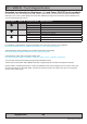
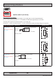
DIGITAL OUPUT (X1 DIG OUT):
Relay Software Control Signals (API) Symbol with references to actual pin assignments (3 digits)
K1 K1_EN
K1_DIS
X1 - Out: 011 (COM)
X1 - Out: 014 (NO)
X1 - Out: 012 (NC)
Mechanical relay.
No internal fuse.
Rated current = 3A.
Voltage = 0-265VAC, 0-32VDC.
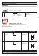
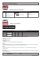
DIGITAL OUTPUT (X1 DIG OUT):
Note: Applies for 8/13 inch units with Intel® Atom™ CPU.
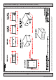
Brief explanation for X1 DIG OUT
HS and AIPC_HS1 signals, managed via software, controls the HS1 relay. In a closed state,
the pin X1 - Out: 041 (OUT+) and pin X1 - Out: 042 (OUT1-) are shortened.
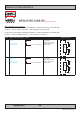
AIPC_HS2 signals, managed via software, controls the HS2 relay. In a closed state,
the pin X1 - Out: 031 (COM) and Pin X1 - Out: 032 (NO) are shortened.
Relay Software Control Signals (API) Symbol Application Circuit
HS1 HS_EN
HS_DIS
AIPC_HS1_EN
AIPC_HS1_DIS
X1 - Out: 041 (OUT+)
X1 - Out: 042 (OUT-)
15 Ohm Solid State Relay.
Not fused.
Rated current = 60mA.
Nominal voltage = 24V.
Isolated output.
Unit
041
042
Option
Load
Option
Load
24VDC
Power return
HS2 AIPC_HS2_EN
AIPC_HS2_DIS
X1 - Out: 031 (COM)
X1 - Out: 032 (NO)
15 Ohm Solid State Relay.
Not fused.
Rated current = 60mA.
Nominal voltage = 24V.
Isolated output.
Unit
031
032
Option
Load
Option
Load
24VDC
Power return