
Instruction Manual

60
Detailed IO Specications
Appendix
IND100077-149
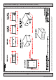
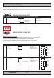
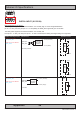
DIGITAL OUTPUT: (X1 DIG OUT):
Relay Software Control Signals (API) Symbol with references to actual pin assignments (3 digits)
K2/RELAY Intel® Atom™ Models:
AIPC_K2_EN
AIPC_K2_DIS
Intel® Core™2 Duo Models:
CPLD_RELAY_EN
CPLD_RELAY_DIS
X1 - Out: 021 (COM)
X1 - Out: 024 (NO)
X1 - Out: 022 (NC)
Mechanical relay.
No internal fuse.
Current = 3A.
Voltage = 0-265VAC, 0-32VDC.
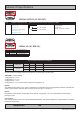
SERIAL I/O: (X7 SER I/O):
PIN 01 X7 - In: 71 Rx+ (Receive Data +)
PIN 02 X7 - In: 72 Rx- (Receive Data -)
PIN 03 X7 - Out: 73 Tx+ (Transmit Data +)
PIN 04 X7 - Out: 74 Tx- (Transmit Data -)
PIN 05 X7 - GND: 75 SGnd (Signal Ground)
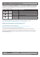
The following modes can be configured:
Conguration RS-422 / RS-485 TX RX BIOS Name
0
Half Duplex
Master RTS Enabled Half duplex master mode, with echo. TX controlled by RTS
1 Slave RTS RTS-Inversed Half duplex slave mode, without echo. TX controlled by RTS
2
Full Duplex
Master Enabled Enabled Full duplex master mode, TX always enabled
3 Slave RTS Enabled Full duplex slave mode, TX controlled by RTS
TX and RX refer to enabling of RX and TX interface on the RS-422 / RS-485 driver.
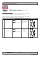
JSETCOM1: Jumper settings:
Configuration 0: 3-4, 5-6
Configuration 1: 4-5, 7-8
Configuration 2: 1-2, 3-4
Configuration 3: 3-4, 5-6 (same jumper setting as Configuration 0).
Default:
The default jumper setting is 3-4, and 5-6, meaning that configuration 0 and 3 is supported by default. To enable half
duplex communication mode the cable connector must short pin 1-3 and pin 2-4.
Option:
If the default communication configuration is not desired, configuration 1 or 2 must specifically be ordered when
placing the order.
Flow Control:
The onboard serial port does not support hardware handshake. The software application is responsible for controlling
Request To Send (RTS).