USER MANUAL Series 1 - Maritime Multi Computer Models JH 15T17 MMC-xxx-Axxx - 15.0 inch Maritime Multi Computer JH 15T17 MMC-xxx-Axxx - 15.0 inch Maritime Multi Computer (LED version) JH 19T14 MMC-xxx-Axxx - 19.0 inch Maritime Multi Computer JH 19T14 MMC-xxx-Axxx - 19.0 inch Maritime Multi Computer (LED version) User Manual MMC Series 1 Updated: 09 Apr 2015 Doc Id: INB100216-1 (Rev 13) Created: 363 Approved: 6405 Please visit www.hatteland-display.com for the latest electronic version of this manual.
Copyright © 2015 Hatteland Display AS Stokkastrandvegen 87B, N-5578 Nedre Vats, Norway. All rights are reserved by Hatteland Display AS. This information may not, in whole or in part, be copied, photocopied, reproduced, translated or reduced to any electronic medium or machinereadable form without the prior written consent of Hatteland Display AS. Review also: www.hatteland-display.com/pdf/misc/doc100703-1_permission_to_create_user_manuals.
Contents Contents........................................................................................... 3 Contents of package........................................................................................... 5 General............................................................................................. 7 About this manual............................................................................................... 8 About Hatteland Display..............................................
Contents Technical Drawings....................................................................... 35 Technical Drawings - JH 15T17 MMC-xxx-Axxx............................................... 36 Standard Version......................................................................................... 36 Technical Drawings - JH 19T14 MMC-xxx-Axxx............................................... 37 Standard Version.........................................................................................
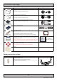
Contents of package Item Description 1 pcs of power cable European Type F “Schuko” to IEC. Length 1.8m Illustration EUR TYPE F IEC Note: Included in package for models with AC input. FS-CABLE EU 1 pcs of power cable US Type B plug to IEC. Length 1.8m US TYPE B IEC Note: Included in package for models with AC input. 80099 1 pcs of DC Power Input housing with internal cable screw terminal. Note: Included in package for models with DC input.
This page left intentionally blank 6
General 7
Hatteland Display AS About this manual The manual contains electrical, mechanical and input/output signal specifications. All specifications in this manual, due to manufacturing, new revisions and approvals, are subject to change without notice. However, the last update and revision of this manual are shown both on the frontpage and also in the “Revision History” chapter at the end of the manual.
Panel Computers Series 1 Maritime Multi Computer (MMC) - Introduction All Series 1 panel computers are based around the high quality, rugged Series 1 displays. With a panel computer though, the displays come with a ‘built-in’ computer, instantly transforming them into navigation and automation powerhouses, ideal for a whole range of different systems and solutions.
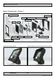
Basic Construction Basic Construction - Series 1 Touch Screen (option) Sun Visor (option) Centerbox Water Cover (option) Mounting Bracket (option) Mechanics Glass TFT Casing Front Frame Bonding Electronics / PCB’s Rotary Bracket (option) User Controls Logo label (option) Example with mounting bracket General IND100077-75 Example with sun visor, mounting bracket and rotary bracket 10
Product Labeling Introduction This section details the locations, content details and specifications for factory mounted labels for all currently available standard Hatteland Display Maritime Multi Computer (MMC) - Series 1 models. This information will in most cases also apply for most Customized Models as well, but may differ based on customer requirements, in that case, please refer to the customized User Manual (paper or electronic version, dependent on customer requirements).
Product Labeling Label Locations Number ID and coloring based on “Label Size and Types“ table from previous page. All illustrations below is seen from rear (and side where needed) with connectors facing down. Actual labels regarding its size and text orientation vs product size is drawn in. Due to space restrictions on selected units, some labels will be rotated 90 degrees to fit properly.
Product Labeling Warranty Label If you are to perform service on a unit still under warranty, any warranty will be void if this label show signs of removal attempts (re-gluing) or removed completely*. This label is located on the back of the product and covers a key screw. This is to aid service departments to determine if there has been any unauthorized service on a unit still under warranty.
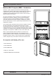
Product Labeling Front Hatch Logo Label The Hatteland Display MMC front frame design offers an area for customized logo hatch label. This hatch/label can be ordered and customized with your own logo delivered from us. The hatch is IP66 rated to protect the front mounted connector(s) behind the hatch. The measurements are as follows. WxH = 181.66 x 44.16mm / 7.15” x 1.74”. R4.10 - 4 places in each corner. Depth of area is 0.5mm.
Touch screen products Introduction to products with touch screen Both Resistive and Capacitive touch screen solutions are used for our products. Please review specifications found in this manual or our website (www.hatteland-display.com) to find your exact type number and then determine if it uses Resistive or Capacitive. Capacitive Touch screen The glass overlay has a coating that stores the charge deposited over its surface electrically.
Touch screen products Touch Screen Drivers and Documentation All units are shipped with a Documentation and Drivers DVD or CD which contains suitable drivers for touch screens. (Named MEDIA STD01). You can also visit our website www.hatteland-display.com to view the same list (or even recently new added products) for our models with touch screen. Before using the touch screen, it should be calibrated for your system. Please install the 3rd party software and use the Calibrate function.
Installation 17
General Installation Recommendations Installation and mounting 1. Most of our products are intended for various methods of installation or mounting (panel mounting, bracket mounting, ceiling/wall mounting etc.); for details, please see the relevant mechanical drawings. 2. Adequate ventilation is a necessary prerequisite for the life of the product. The air inlet and outlet openings must definitely be kept clear; coverings which restrict ventilation are not permissible. 3.
General Installation Recommendations 6. When a product is being installed, the surface base or bulkhead must be checked to ensure that it is flat in order to avoid twisting of the unit when the fixing screws are tightened, because such twisting would impair mechanical functions. Any unevenness should be compensated for by means of spacing-washers. 7. This Product shall be grounded to protective Earth.
General Installation Recommendations Cables Use only high quality shielded signal cables. Cable Entries & Connectors (Marked area) - Illustration only Bottom View Back View Maximum Cable Length Any cable should generally be kept as short as possible to provide a high quality input/output. The maximum signal cable length will depend on the signal resolution and frequency, but also on the quality of the signal output from the computer/radar.
General Installation Recommendations Rotary Bracket and Mounting Bracket (15 inch) combined assembling Illustration shows “Mounting Bracket JH 15TBR STD-A1” and “Rotary Bracket JH 15TRO STD-A1 (15 inch only)” combined. Both brackets are available separately and are delivered as such. Both brackets contains several parts (as indicated). The table below illustrates a complete mounting of these two and you have to disassemble the “Mounting Bracket” prior to combining the two brackets together.
General Installation Recommendations Rotary Bracket and Mounting Bracket (17-26 inch) combined assembling Illustration below shows “Mounting Bracket” and “Rotary Bracket JH MMDRO STD-A1 (17 to 26 inch)” combined. Both brackets are available separately and are delivered as such. Both brackets contains several parts (as indicated). The table below illustrates a complete mounting of these two and you have to disassemble the “Mounting Bracket” prior to combining the two brackets together.
Physical Connections - MMC / xxC based units Connection area of unit (illustration) PS/2 Mouse + internal miniPCI slot Parallel (LPT) USB 2,3,4,5 COM1, COM2 PS/2 Keyboard 2 x GigaBit LAN DVI-I/RGB OUT Compact Flash Reader Power Input AC or DC Grounding Screw: Please review “General Installation Chapter”, pt. 7 for more information. Cable Tension To reduce tension of the cables you connect, secure them with a cable tie to the base mounted clamp or to the chassis hinges.
Physical Connections - MMC / xxC based units DVI-I OUT: DVI/RGB OUT enables a direct clone signal output from the computer. You may choose to use a DVI-I 29P cable directly or use a DVI-I -> RGB adapter to use a RGB/VGA HD D-SUB 15P instead for this purpose. Connect the cable to the Connector (female) and secure it to the hex spacers provided on the unit. Connect the other end to your equipment and secure it.
Operation MMC Products 25
User Controls USER CONTROLS OVERVIEW The units are available as two different factory user control configurations illustrated below. Buzzer Potmeter Keypad w/Status LED ring #1: Potmeter, Buzzer and Keypad Control with its Status LED Ring. Brightness for the unit is adjusted by turning the potmeter clockwise or anti-clockwise. The tactile keypad function as ON/OFF switch. The buzzer aperture provide audible alarm for systems that require/supports it.
User Controls KEYPAD FUNCTIONALITIES (unit model dependable) Not in use Power button Push Buttons Right button Left button Status LED Ring Not in use MENU/POWER ICON function as: Power On/Off. Note: MENU OSD is not available on MMC units. LEFT (◄) function as: Decrease Brightness. RIGHT (►) function as: Increase Brightness. UP (+) function as: No function on MMC units. DOWN (-) function as: No function on MMC units.
Status LED Overview Status LED Overview The unit features a multi purpose indicator LED status ring which through different patterns and realtime activity gives back the status of the signal detected, power on/off, calibration, menu activity and more. The LEDs are multicolored which either illuminate green or red, based on the activity. OFF (No power connected) OFF (Standby, power detected) ON (Signal Search) 8 LED OFF 8 RED LED STATIC ON 1 GREEN LED MOVEMENT looping.
Specifications 29
Specifications - JH 15T17 MMC-xxx-Axxx (CCFL version) SPECIFICATIONS Note: All specifications are subject to change without prior notice! Please visit www.hatteland-display.com for the latest electronic version. All specifications are subject to change without prior notice! TFT Technology: • • • • Physical Dimensions: High Quality SHARP TFT 15.0 inch viewable image size Color Active Matrix LCD Module a-Si Thin Film Transistor (TFT) • 412.00 (W) x 345.00 (H) x 73.28 (D) mm • 16.22" (W) x 13.
Specifications - JH 15T17 MMC-xxx-Axxx (LED version) SPECIFICATIONS Note: All specifications are subject to change without prior notice! Please visit www.hatteland-display.com for the latest electronic version. All specifications are subject to change without prior notice! TFT Technology: Physical Dimensions: • High Quality TFT with LED Backlight Technology • 15.0 inch viewable image size, Aspect Ratio 4:3 • TFT active-matrix liquid crystal panel • 412.00 (W) x 345.00 (H) x 73.28 (D) mm • 16.
Specifications - JH 19T14 MMC-xxx-Axxx (CCFL version) SPECIFICATIONS Note: All specifications are subject to change without prior notice! Please visit www.hatteland-display.com for the latest electronic version. All specifications are subject to change without prior notice! TFT Technology: Physical Considerations: • • • • • W:483.00 [19.02''] x H:444.00 [17.48''] x D:82.00 [3.23''] mm [inch] • Weight: 11 kg (approx) High Quality TFT with LED Backlight Technology 19.
Specifications - JH 19T14 MMC-xxx-Axxx (LED version) SPECIFICATIONS Note: All specifications are subject to change without prior notice! Please visit www.hatteland-display.com for the latest electronic version. All specifications are subject to change without prior notice! TFT Technology: Physical Considerations: • • • • • W:483.00 [19.02''] x H:444.00 [17.48''] x D:82.00 [3.23''] mm [inch] • Weight: 11 kg (approx) High Quality TFT with LED Backlight Technology 19.
This page left intentionally blank 34
Technical Drawings 35
This document is the property of Hatteland Display AS. This document and any authorized reproduction thereof, must not be used in any way against the interest of Hatteland Display AS. Any authorized reproduction, in whole or in part, must include this legend. Hatteland Display Proprietary information. Not to be distributed to any third party without written permission. Dimensions might be shown with or without decimals and indicated as mm [inches]. Tolerance on drawings is +/- 1mm.
This document is the property of Hatteland Display AS. This document and any authorized reproduction thereof, must not be used in any way against the interest of Hatteland Display AS. Any authorized reproduction, in whole or in part, must include this legend. Hatteland Display Proprietary information. Not to be distributed to any third party without written permission. Dimensions might be shown with or without decimals and indicated as mm [inches]. Tolerance on drawings is +/- 1mm.
This page left intentionally blank 38
Technical Drawings - Accessories 39
This document is the property of Hatteland Display AS. This document and any authorized reproduction thereof, must not be used in any way against the interest of Hatteland Display AS. Any authorized reproduction, in whole or in part, must include this legend. Hatteland Display Proprietary information. Not to be distributed to any third party without written permission. Dimensions might be shown with or without decimals and indicated as mm [inches]. Tolerance on drawings is +/- 1mm.
This document is the property of Hatteland Display AS. This document and any authorized reproduction thereof, must not be used in any way against the interest of Hatteland Display AS. Any authorized reproduction, in whole or in part, must include this legend. Hatteland Display Proprietary information. Not to be distributed to any third party without written permission. Dimensions might be shown with or without decimals and indicated as mm [inches]. Tolerance on drawings is +/- 1mm.
This document is the property of Hatteland Display AS. This document and any authorized reproduction thereof, must not be used in any way against the interest of Hatteland Display AS. Any authorized reproduction, in whole or in part, must include this legend. Hatteland Display Proprietary information. Not to be distributed to any third party without written permission. Dimensions might be shown with or without decimals and indicated as mm [inches]. Tolerance on drawings is +/- 1mm.
This document is the property of Hatteland Display AS. This document and any authorized reproduction thereof, must not be used in any way against the interest of Hatteland Display AS. Any authorized reproduction, in whole or in part, must include this legend. Hatteland Display Proprietary information. Not to be distributed to any third party without written permission. Dimensions might be shown with or without decimals and indicated as mm [inches]. Tolerance on drawings is +/- 1mm.
This document is the property of Hatteland Display AS. This document and any authorized reproduction thereof, must not be used in any way against the interest of Hatteland Display AS. Any authorized reproduction, in whole or in part, must include this legend. Hatteland Display Proprietary information. Not to be distributed to any third party without written permission. Dimensions might be shown with or without decimals and indicated as mm [inches]. Tolerance on drawings is +/- 1mm.
This document is the property of Hatteland Display AS. This document and any authorized reproduction thereof, must not be used in any way against the interest of Hatteland Display AS. Any authorized reproduction, in whole or in part, must include this legend. Hatteland Display Proprietary information. Not to be distributed to any third party without written permission. Dimensions might be shown with or without decimals and indicated as mm [inches]. Tolerance on drawings is +/- 1mm.
This document is the property of Hatteland Display AS. This document and any authorized reproduction thereof, must not be used in any way against the interest of Hatteland Display AS. Any authorized reproduction, in whole or in part, must include this legend. Hatteland Display Proprietary information. Not to be distributed to any third party without written permission. Dimensions might be shown with or without decimals and indicated as mm [inches]. Tolerance on drawings is +/- 1mm.
This document is the property of Hatteland Display AS. This document and any authorized reproduction thereof, must not be used in any way against the interest of Hatteland Display AS. Any authorized reproduction, in whole or in part, must include this legend. Hatteland Display Proprietary information. Not to be distributed to any third party without written permission. Dimensions might be shown with or without decimals and indicated as mm [inches]. Tolerance on drawings is +/- 1mm.
This document is the property of Hatteland Display AS. This document and any authorized reproduction thereof, must not be used in any way against the interest of Hatteland Display AS. Any authorized reproduction, in whole or in part, must include this legend. Hatteland Display Proprietary information. Not to be distributed to any third party without written permission. Dimensions might be shown with or without decimals and indicated as mm [inches]. Tolerance on drawings is +/- 1mm.
This document is the property of Hatteland Display AS. This document and any authorized reproduction thereof, must not be used in any way against the interest of Hatteland Display AS. Any authorized reproduction, in whole or in part, must include this legend. Hatteland Display Proprietary information. Not to be distributed to any third party without written permission. Dimensions might be shown with or without decimals and indicated as mm [inches]. Tolerance on drawings is +/- 1mm.
This document is the property of Hatteland Display AS. This document and any authorized reproduction thereof, must not be used in any way against the interest of Hatteland Display AS. Any authorized reproduction, in whole or in part, must include this legend. Hatteland Display Proprietary information. Not to be distributed to any third party without written permission. Dimensions might be shown with or without decimals and indicated as mm [inches]. Tolerance on drawings is +/- 1mm.
This document is the property of Hatteland Display AS. This document and any authorized reproduction thereof, must not be used in any way against the interest of Hatteland Display AS. Any authorized reproduction, in whole or in part, must include this legend. Hatteland Display Proprietary information. Not to be distributed to any third party without written permission. Dimensions might be shown with or without decimals and indicated as mm [inches]. Tolerance on drawings is +/- 1mm.
This document is the property of Hatteland Display AS. This document and any authorized reproduction thereof, must not be used in any way against the interest of Hatteland Display AS. Any authorized reproduction, in whole or in part, must include this legend. Hatteland Display Proprietary information. Not to be distributed to any third party without written permission. Dimensions might be shown with or without decimals and indicated as mm [inches]. Tolerance on drawings is +/- 1mm.
This document is the property of Hatteland Display AS. This document and any authorized reproduction thereof, must not be used in any way against the interest of Hatteland Display AS. Any authorized reproduction, in whole or in part, must include this legend. Hatteland Display Proprietary information. Not to be distributed to any third party without written permission. Dimensions might be shown with or without decimals and indicated as mm [inches]. Tolerance on drawings is +/- 1mm.
This page left intentionally blank 54
Appendixes 55
Pinout Assignments - Common Connectors Note: Not all connectors may be available on your specific product. This depends on the amount of additional hardware installed from factory, or customized solutions. These pin assignments are for the common connectors used. Connectors are seen from users Point Of View (POV).
Pinout Assignments - Common Connectors 25P Parallel 13 12 11 10 9 8 7 6 5 4 3 2 1 25 24 23 22 21 20 19 18 17 16 15 14 Pin 01 - STROBE Pin 02 - DATA0 Pin 03 - DATA1 Pin 04 - DATA2 Pin 05 - DATA3 Pin 06 - DATA4 Pin 07 - DATA5 Pin 08 - DATA6 Pin 09 - DATA7 Pin 10 - ACK Pin 11 - BUSY Pin 12 - PE Pin 13 - SELECT Pin 14 - AUTO FEED Pin 15 - ERR# Pin 16 - INIT# Pin 17 - SLIN# Pin 18 - GND Pin 19 - GND Pin 20 - GND Pin 21 - GND Pin 22 - GND Pin 23 - GND Pin 24 - GND Pin 25 - GND This signal indicates to the print
Pin Assignments - Common Connectors (Additional) Pin Assignments - 9P Serial COM RS-485/RS-422 Full Duplex Mode 5 4 3 2 1 Pin Assignments - 9P Serial COM RS-485/RS-422 Half Duplex Mode 5 4 3 2 1 9 8 7 6 Pin 01 - N/C Pin 02 - TXPin 03 - RX+ Pin 04 - N/C Pin 05 - GND Pin 06 - N/C Pin 07 - TX+ Pin 08 - RXPin 09 - N/C 9 8 7 6 Not Connected Transmit Data Receive Data + Not Connected Ground Not Connected Transmit Data + Receive Data Not Connected Pin 01 - N/C Pin 02 - N/C Pin 03 - DAT+ Pin 04 - N/C Pin 05 -
Basic Trouble-shooting GENERAL ISSUES FOR TFT PANEL BASED PRODUCTS Note: Applies for a range of various products. This is only meant as a general guide. NO PICTURE / LED BEHAVIOUR: If there is no light at all in the LED at the FRONT, check power cables. If the LED in front is green then check if the brightness is set/adjusted to max brightness. Lack of image is most likely to be caused by incorrect connection, lack of power or wrong BIOS settings.
Declaration of Conformity We, manufacturer, Hatteland Display AS, Stokkastrandvegen 87B, N-5578 Nedre Vats, Norway declare under our sole responsibility that the JH MMD, JH MMC, JH STD, JH MIL, HM NMD, HM MIL, HM CMD, HT STD, HD MMD, HM MMD, HT MMC, HD MMC and HT/HM (computers) product ranges is in conformity with the following standards in accordance with the EMC Directive.
Return Of Goods Information Return of goods: (Applies not to warranty/normal service/repair of products) Hatteland Display referenced as “manufacturer” in this document. Before returning goods, please contact your system supplier before sending anything directly to manufacturer. When you return products after loan, test, evaulation or products subject for credit, you must ensure that all accessories received from our warehouse is returned.
General Terms and Conditions As of January 2015, Hatteland Display AS’ “Terms of Sales and Delivery” and “Warranty Terms” has been substituted by the updated ”General terms and conditions for sale of goods and performance of additional services” (the “General Terms and Conditions”).
Pixel Defect Policy PIXEL DEFECT POLICY Dot-defects (Bright or dark spots on the panel) Due to the effect that dot failures are part of the TFT technology such failure occurrence cannot be prevented basically. Even though dot defects usually occur during production process, new defects can appear within the lifespan of a TFT display. Neither the production at LCD-supplier nor the use of a LCD-Monitor after shipment can be influenced by Hatteland Display.
Notes General Notes: (For all products) - The unit is type approved according to EN60945 4th, 4.4, equipment category b) protected from the weather. - Other type approvals applies for the different products. Please see Testing & Approvals Overview section in this manual for more information. - Use of brightness and push buttons may inhibit visibility of information at night. - License Terms for the installed OEM Operating System (OS) can be found on root of main boot device, (typically “C:\” partition).
Revision History Rev. 0 1 2 3 4 5 6 7 8 By SE JE SE AK BU SE JE SE KO SE JE AK SE BB MB AK SE BB SE SE 9 10 SE GOS BB SE 11 JE SE KK SE PG MJL SE 12 13 Date 20 Aug 2009 Release for internal review. 02 Oct 2009 Official release for internet. Notes 05 Nov 2009 Removed text for Capacitive touch screen. Page 11. Removed LRS type approval (pending) from specifications, page 28, 29 Added note about 15 inch with resistive touch screen & bonding, specifications page 28.
w ww.hat tel and-di sp l ay .