
Instruction Manual

Pinout Assignments - Common Connectors
57
IND100241-2
Appendix
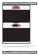
25P Parallel
Pin 01 - STROBE This signal indicates to the printer that data at PD7..0 are valid.
Pin 02 - DATA0 Parallel data bus from PC board to printer. The data line are able to operate in PS/2 compatible bi-directional mode.
Pin 03 - DATA1 Same as Pin 02
Pin 04 - DATA2 Same as Pin 02
Pin 05 - DATA3 Same as Pin 02
Pin 06 - DATA4 Same as Pin 02
Pin 07 - DATA5 Same as Pin 02
Pin 08 - DATA6 Same as Pin 02
Pin 09 - DATA7 Same as Pin 02
Pin 10 - ACK Signal from printer indicating that the printer has received the data and is ready to accept further data.
Pin 11 - BUSY Signal from printer indicating that the printer cannot accept further data.
Pin 12 - PE Signal from printer indicating that the printer is out of paper.
Pin 13 - SELECT Signal from printer to indicate that the printer is selected.
Pin 14 - AUTO FEED This active low output causes the printer to add a line feed after each line printed.
Pin 15 - ERR# Signal from printer indicating that an error has been detected.
Pin 16 - INIT# This active low output initialises (resets) the printer.
Pin 17 - SLIN# Signal to select the printer sent from CPU board to printer.
Pin 18 - GND Ground
Pin 19 - GND Ground
Pin 20 - GND Ground
Pin 21 - GND Ground
Pin 22 - GND Ground
Pin 23 - GND Ground
Pin 24 - GND Ground
Pin 25 - GND Ground
13 12 11 10 9 8 7 6 5 4 3 2 1
25 24 23 22 21 20 19 18 17 16 15 14
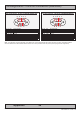
24P DVI-D & DVI-I
Pin 01 T.M.D.S. Data2 - (Digital - RED link 1)
Pin 02 T.M.D.S. Data2 + (Digital + RED link 1)
Pin 03 T.M.D.S. Data2/4 Shield
Pin 04 T.M.D.S. Data4 - (Digital - GREEN link 2)
Pin 05 T.M.D.S. Data4 + (Digital + GREEN link 2)
Pin 06 DDC Clock
Pin 07 DDC Data
Pin 08 Analog Vertical Sync (DVI-I only)
Pin 09 T.M.D.S. Data1 - (Digital - GREEN link 1)
Pin 10 T.M.D.S. Data1 + (Digital + GREEN link 1)
Pin 11 T.M.D.S. Data1/3 Shield
Pin 12 T.M.D.S. Data3 - (Digital - BLUE link 2)
Pin 13 T.M.D.S. Data3 + (Digital + BLUE link 2)
Pin 14 +5V Power (for standby mode)
Pin 15 Ground (for +5V and analog sync)
Pin 16 Hot Plug Detect
Pin 17 T.M.D.S. Data0 - (Digital - BLUE link 1) and digital sync.
Pin 18 T.M.D.S. Data0 + (Digital + BLUE link 1) and digital sync.
Pin 19 T.M.D.S. Data0/5 Shield
Pin 20 T.M.D.S. Data5 - (Digital - RED link 2)
Pin 21 T.M.D.S. Data5 + (Digital - RED link 2)
Pin 22 T.M.D.S. Clock Shield
Pin 23 T.M.D.S. Clock + (Digital clock + (Links 1 and 2)
Pin 24 T.M.D.S. Clock - (Digital clock - (Links 1 and 2)
Pin C1 Analog RED
Pin C2 Analog GREEN
Pin C3 Analog BLUE
Pin C4 Analog Horizontal Sync.
Pin C5 Analog Ground (return for RGB signals)
DDC = Display Data Channel /// T.M.D.S = Transition Minimized Differential Signal /// PIN C1,C2,C3,C4 = Only present on DVI-I connectors.
NOTE: Connector shows a DUAL LINK design, but some units may not support it. Only products with 1920x1200 or more in resolution
require / support DUAL LINK.
1 2 3 4 5 6 7 8 C1 C2
9 10 11 12 13 14 15 16 C5
17 18 19 20 21 22 23 24 C3 C4
Additional connector pinouts may be available in third party motherboard manuals, primarily for computers only.
Please see manual/drivercd delivered with your product or own section in this user manual.