
Manual


25
IND100133-32
RGB IN
AC Power Input
Multifunction Conn.
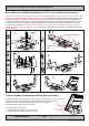
Connection area of unit (illustration)
Cable Tension
To reduce tension of the cables you connect,
secure them with a cable tie to the base mounted
clamp or to the chassis hinges.
For certain units a base mounted clamp is
available (FIG 1). For other models a hinge in
the chassis is available (FIG 2).
FIG 1
FIG 2
Physical Connections
AC Power OuputUSB I/O
DVI-I IN
RGB OUT
DC Power Input
GROUNDING SCREW:
Please review “General Installation Chapter”, pt. 7 for more information.
USB I/O:
This USB TYPE B connector is reserved for customized solutions. One customized example could be to connect it
to a computer USB connection via a TYPE B-A cable and then accessing it via a front USB TYPE A connector on the
front frame bezel to utilize a mouse or other control device.
RGB IN:
Connect the VGA cable to the D-SUB 15P Connector (female). Secure the VGA cable to the hex spacers provided on
the unit and make sure you do not bend any of the pins inside the connector when connecting. Connect the other end
of the cable to the VGA connector on your equipment and secure it.
RGB OUT:
RGB OUT enables a direct clone of the incoming VGA (RGB1) signal. Connect the cable to the D-SUB 15P Connector
(female) and secure it to the hex spacers provided on the unit. Connect the other end to your equipment and secure
it. Note that DVI inputs is NOT cloned, even though if the DVI-I connector has been configured with the DVI-I > RGB
adapter to use a RGB signal as input.
Grounding Screw