TECHNICAL MANUAL Serial/Ethernet Communication Control Interface (SCOM) Applies for Series X Maritime Multi Display (MMD/STD) product range: HD 12T21 xxD-xxx-Fxxx HD 15T21 xxD-xxx-Fxxx HD 17T21 xxD-xxx-Fxxx HD 19T21 xxD-xxx-Fxxx HD 24T21 xxD-xxx-Fxxx HD 26T21 xxD-xxx-Fxxx Applies for Series X Maritime Multi Computer (MMC) product range: HD 12T21 xxC-xxx-Fxxx HD 15T21 xxC-xxx-Fxxx HD 17T21 xxC-xxx-Fxxx HD 19T21 xxC-xxx-Fxxx HD 24T21 xxC-xxx-Fxxx HD 26T21 xxC-xxx-Fxxx Technical Manual SCOM Series X Updated:
Copyright © 2015 Hatteland Display AS Stokkastrandvegen 87B, N-5578 Nedre Vats, Norway. All rights are reserved by Hatteland Display AS. This information may not, in whole or in part, be copied, photocopied, reproduced, translated or reduced to any electronic medium or machinereadable form without the prior written consent of Hatteland Display AS. Review also: www.hatteland-display.com/pdf/misc/doc100703-1_permission_to_create_user_manuals.
Contents Contents.................................................................................................. 3 Introduction............................................................................................ 5 Serial Interface Configuration............................................................................................................... 5 Ethernet Interface Configuration...........................................................................................................
Contents Appendixes........................................................................................... 36 HEX, ASCII, BIN and Character table................................................. 37 C# / Pseudo Ethernet/TCP Code example.......................................... 42 Notes................................................................................................... 43 Revision History..................................................................................
Serial/Ethernet Communication (SCOM) Interface Introduction This document defines the electrical interface, serial data format, and communication protocols of the Communication Control Interface (SCOM). The purpose of this interface is to enable a computer application to control one or more units. Units refer to either displays or panel computers. Serial Interface Configuration The serial interface can have different configurations, selected by the OSD menu.
Serial/Ethernet Communication (SCOM) Interface Installing API/VCOM Drivers In order to access and communicate with the Panel Computer (MMC) units (no need on MMD/STD, use SCOM), it may or may not already have pre-installed drivers depending on factory defaults. If you need to install or re-install drivers, please follow the instructions as described below: Note: Drivers available for Microsoft® Windows® Operating System only (32 and 64bit).
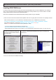
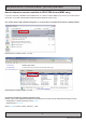
Serial/Ethernet Communication (SCOM) Interface How to determine version installed of API/VCOM drivers (MMC only) If you have previously installed the API/VCOM drivers on a Panel Computer (MMC), here is how you can find version information via several methods (Microsoft® Windows® Operating systems only): Via “Control Panel / Add or Remove Programs” or “Control Panel / Programs and Features” (OS dependent): Example above indicates version “1.3.385”. Example above indicates version “1.3.266”.
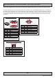
Serial/Ethernet Communication (SCOM) Interface For Pin Out assignments, please review the following diagrams that covers all units and connector types: Connectors illustrated here are either standard by factory default or may be available (through factory customization). Note that some combinations may not be possible due to space restrictions. List also valid for customized models. All pin out assignments are seen from users Point of View (POV) while looking straight at the connector.
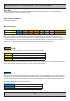
Serial/Ethernet Communication (SCOM) Interface Data Rates The unit is configured to transmit and receive data at 9600 bits/second (Serial mode) or via standard Ethernet 10/100/1000Mbps connection through port 10001. Data Format Serial Mode Data shall be transmitted with no parity, 8 data bits, one start bit and one stop bit. XON/XOFF flow control should be switched off/disabled. Message Format The basic message format shall be as follows: Byte # 0 1 2 3 4 5 6 7..
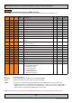
Serial/Ethernet Communication (SCOM) Interface CMD Message Commands and Queries (CMD) Contents The command can be one of the following values and consists always of 3 bytes in positions 2,3,4: Byte 2 Byte 3 Byte 4 ASCII Description I/O Unit Type Page 0x42 0x52 0x49 "BRI" Backlight Minimum Value W all 12 0x42 0x52 0x4C "BRL" Set LED Glass Display Control™ (GDC) Brightness R/W xxC 12 0x42 0x52 0x4D "BRM" Backlight Maximum Value W all 12 0x42 0x52 0x54 "BRT" User Brightness C
Serial/Ethernet Communication (SCOM) Interface LEN Data Length (LEN) This single byte defines the length of DATA in the message in bytes. The maximum value for this field is 74 bytes (0x4A in HEX). The minimum value is 0 bytes (0x00 in HEX). IHCHK Inverse Header Checksum (IHCHK) This single byte is a simple 8-bit checksum of the header data, message bytes 0 to 5 on which a bit-wise inversion has been performed. The checksum shall be initialised to 0.
Serial/Ethernet Communication (SCOM) Interface "BRI" - Backlight Minimum Value Set the backlight minimum value. Range from 0x00 to 0xFF (0% - 100%). Example: Command to set 50% Brightness: 0x07 0xFF 0x42 0x52 0x49 0x01 0x1B 0x80 0x7F "BRL" - Set LED Glass Display Control™ (GDC) Brightness Set the backlight intensity for the Glass Display Control™ (GDC) LED's on the front glass. From 0x00 to 0x31 (0% 100%). The brightness value shall be sent as 1 byte in the DATA field.
Serial/Ethernet Communication (SCOM) Interface "BRT" - User Brightness Control This command is sent to the unit to command the backlight brightness control setting.The brightness value shall be sent as one byte in the DATA field. A setting of 0x00 will indicate off. A setting of 0xFF (255 in value) will indicate maximum brightness. Intermediate values will control brightness over the range from minimum to maximum luminance. LEN = one data byte. After any power cycle the BRT will be set to 100%.
Serial/Ethernet Communication (SCOM) Interface "BZZ" - Buzzer Control This command is sent to the unit to control buzzer on/off if there is a buzzer present. LEN = one data byte. 0x00 0xFF Turn the buzzer off Turn the buzzer on If the data checksum is valid, the unit will reply to this command with an ACK attention code. The DATA field will indicate the buzzer state.
Serial/Ethernet Communication (SCOM) Interface Example: Command for query num of packets: 0x07 0xFF 0x44 0x4C 0x3F 0x00 0x2A 0x01 0x2A Acknowledge: DL? indicates 4 available packets: 0x06 0xFF 0x44 0x4C 0x3F 0x03 0xFC Continued on next page... Tip for knowing which Slot that contains possible ECDIS table if DL? command responds NAK (negative response), is to send a Query "MCC" command prior to a "DL?" query. Follow the procedure below.
Serial/Ethernet Communication (SCOM) Interface "DLN" - Download ECDIS package table x Before sending this command, use "DL?" to retrieve how many packets are actually available in the ECDIS table. If you request a download package from a empty slot or above the available packets in memory, you will get a NAK response. The "DLN" command shall be sent to the unit to request a specific data packet stored in the unit's memory.
Serial/Ethernet Communication (SCOM) Interface "ETC" - Elapsed Time Counter Query The unit features an elapsed time counter which counts the total number of hours that the unit has been operated. No data shall be sent with this command. The unit will reply to this command with an ACK attention code. The DATA field will be set to a 3 byte string, where the most significant byte is transmitted first.
Serial/Ethernet Communication (SCOM) Interface "FWV" - Firmware (FW) Version Video chipset, Cypress and Ethernet controller Get the firmware version for GEV/RAP (Video Chipset), Cypress (Glass Display Control™ - GDC) and Ethernet.
Serial/Ethernet Communication (SCOM) Interface "LIS" - Luminance and Environment Sensor Measurement Sending this command the light sensor on the Glass Display Control™ (GDC) will return a value about luminance of environment.
Serial/Ethernet Communication (SCOM) Interface "POT" - Potentiometer Control The unit may allow the backlight to be controlled by the local control (potentiometer/keypad) mounted on the front of the unit, by the remote control or by the combination of the two. This is valid for the brilliance buttons if no external potentiometer is connected. This command provides means to enable/disable the local control. LEN = one data byte. 0x00 0xFF Disables the local control.
Serial/Ethernet Communication (SCOM) Interface "SWI" - Main Software Version Query The SWI command is a legacy command which is backward compatible with already existing customer setups (i.e. product ranges released before Series X). For newer systems and implementations, please use "FWV" command when possible. Any future revisions, such as CMD additions or changes to the software will increment the software version. The unit will reply to this command with an ACK attention code.
Serial/Ethernet Communication (SCOM) Interface "TYP" - Type/Model Number Query This query is sent to the unit in order to identify the unit type by its model number / part number. No data shall be sent with this query. The unit will reply to this command with an ACK attention code. The DATA field should be translated to an ASCII text string which indicate the specified Type/Model Number, e.g: "HD17T21MMCMJDOABA". FYI: Which translates to "HD 17T21 MMC" (http://www.hatteland-display.
Serial/Ethernet Communication (SCOM) Interface "MCC" - OSD Control Functionality This command gives remote access to the unit’s OSD menu settings. The commands are transmitted in the DATA field. For future products, it can not be guaranteed that all commands will still be available. If the checksum is valid, the unit will reply to this command with an ACK attention code, where the data field contains the original "MCC" command followed by acknowledge from the controller.
Serial/Ethernet Communication (SCOM) Interface MCC Command HUE Control Note: In video mode only Not available on STD units Syntax and Functionality Syntax Details and Values : 07 FF 4D 43 43 03 23 84 xx yy zz Where xx = "0" to "6" Where yy = "0" to "F" Where zz = Calculated Checksum Max Range: "0" "0" to "6" "4" Default: "3" "2" Function Examples: Example "50" : 07 FF Query "?" : 07 FF Reset "R" : 07 FF Reset "r" : 07 FF Increase "+" : 07 FF Decrease "-" : 07 FF Syntax : 07 FF 4D 4D 4D 4D 4D 4D 4D 4
Serial/Ethernet Communication (SCOM) Interface MCC Command Scaling Mode Note: Not available on STD units.
Serial/Ethernet Communication (SCOM) Interface MCC Command LED Drive Select OSD Language Syntax and Functionality Syntax Details and Values : 07 FF 4D 43 43 03 23 94 xx yy zz Function Examples: Example "10" : 07 FF Query "?" : 07 FF Reset "R" : 07 FF Reset "r" : 07 FF Increase "+" : 07 FF Decrease "-" : 07 FF Syntax : 07 FF 4D 4D 4D 4D 4D 4D 4D 43 43 43 43 43 43 43 43 43 43 43 43 43 43 03 02 02 02 02 02 02 23 24 24 24 24 24 24 94 94 94 94 94 94 95 31 3F 52 72 2B 2D xx 30 0A 2C 19 F9 40 3E zz F
Serial/Ethernet Communication (SCOM) Interface MCC Command Gamma (Calibration) Select Note: Available function list differs between MMD and STD units! Syntax and Functionality Syntax Details and Values : 07 FF 4D 43 43 02 24 9D xx zz Function Examples: Example "1" : 07 FF Query "?" : 07 FF Reset "R" : 07 FF Reset "r" : 07 FF 4D 4D 4D 4D 43 43 43 43 43 43 43 43 02 02 02 02 24 24 24 24 9D 9D 9D 9D 31 3F 52 72 31 23 10 F0 Where xx = "0" to "2" or "1" to "2" Where zz = Calculated Checksum Availabl
Serial/Ethernet Communication (SCOM) Interface MCC Command PIP, PBP Contrast Control Syntax and Functionality Syntax Details and Values : 07 FF 4D 43 43 03 23 A3 xx yy zz Function Examples: Example "50" : 07 FF Query "?" : 07 FF Reset "R" : 07 FF Reset "r" : 07 FF Increase "+" : 07 FF Decrease "-" : 07 FF Syntax : 07 FF 4D 4D 4D 4D 4D 4D 4D 43 43 43 43 43 43 43 43 43 43 43 43 43 43 03 02 02 02 02 02 03 23 24 24 24 24 24 23 A3 A3 A3 A3 A3 A3 A4 35 3F 52 72 2B 2D xx 30 F7 1D 0A EA 31 2F yy zz Fu
Serial/Ethernet Communication (SCOM) Interface MCC Command Syntax and Functionality Green Level for Selected Color Syntax : 07 FF Temperature Function Examples: Note: Example "50" : 07 FF Available function list differs Query "?" : 07 FF between MMD and STD units! Reset "R" : 07 FF Reset "r" : 07 FF Increase "+" : 07 FF Decrease "-" : 07 FF Blue Level for Selected Color Syntax : 07 FF Temperature Function Examples: Note: Example "50" : 07 FF Available function list differs Query "?" : 07 FF between MMD an
Serial/Ethernet Communication (SCOM) Interface MCC Command Set IP Address (fixed or auto) Note: By sending this command, the communication mode will be automatically set to "Ethernet", in the "Communication Mode", referenced earlier in this chapter. In addition, a power off/on to the unit is required to reboot the internal network code and utilize the newly set IP address.
Serial/Ethernet Communication (SCOM) Interface MCC Command Load User Default Note: Available function list differs between MMD and STD units! Syntax and Functionality Syntax Details and Values : 07 FF 4D 43 43 02 24 D8 xx zz Function Examples: Example "3" : 07 FF 4D 43 43 02 24 D8 33 F4 Where xx = "1" to "5" Where zz = Calculated Checksum Available functions (MMD): "0" = Read Defaults "1" = User1 Slot "2" = User2 Slot "3" = User3 Slot "4" = User4 Slot "5" = User5 Slot Available functions (STD): "0" =
Serial/Ethernet Communication (SCOM) Interface "?" - Query OSD Command This command can be used to query the unit for the chosen command and it's current operating value. Note that this feature is only available when using the Unit OSD Control "MCC" command. This command is a read-only command which will not change the current value. "R" / "r" - Reset OSD Command This command can be used to reset the unit for the chosen command and it's current operating value.
Serial/Ethernet Communication (SCOM) Interface Operational Requirements The following sections define the operational requirements. Serial Message Failure If serial messages stop being transmitted or are corrupt, the unit will remain at the last commanded brightness. Periodic Messages Commands shall be transmitted to the unit at a repetition no faster than 4 Hz.
Serial/Ethernet Communication (SCOM) Interface Unit Response and Addresses When individual unit addressing is supported by an installed configuration of units in a RS-485 (for units that support it) system, a separate ACK or NAK message for each unit will be transmitted providing each unit’s individual address in response to any broadcast addressed Command. NAK messages will not be generated when an error in a Broadcast message is detected.
This page left intentionally blank 35
Appendixes 36
HEX, ASCII, BIN and Character table HEX 0x00 0x01 DEC 0 1 BIN 00000000 00000001 0x02 0x03 0x04 0x05 0x06 0x07 0x08 0x09 0x0A 0x0B 0x0C 0x0D 0x0E 0x0F 0x10 0x11 0x12 0x13 0x14 0x15 0x16 0x17 0x18 0x19 0x1A 0x1B 0x1C 0x1D 0x1E 0x1F 0x20 0x21 0x22 0x23 0x24 0x25 0x26 0x27 0x28 0x29 0x2A 0x2B 0x2C 0x2D 0x2E 0x2F 0x30 0x31 0x32 2 3 4 5 6 7 8 9 10 11 12 13 14 15 16 17 18 19 20 21 22 23 24 25 26 27 28 29 30 31 32 33 34 35 36 37 38 39 40 41 42 43 44 45 46 47 48 49 50 00000010 00000011 00000100 00000101 0000011
HEX, ASCII, BIN and Character table HEX 0x33 0x34 0x35 0x36 0x37 0x38 0x39 0x3A 0x3B 0x3C 0x3D 0x3E 0x3F 0x40 0x41 0x42 0x43 0x44 0x45 0x46 0x47 0x48 0x49 0x4A 0x4B 0x4C 0x4D 0x4E 0x4F 0x50 0x51 0x52 0x53 0x54 0x55 0x56 0x57 0x58 0x59 0x5A 0x5B 0x5C 0x5D 0x5E 0x5F 0x60 0x61 0x62 0x63 0x64 0x65 DEC 51 52 53 54 55 56 57 58 59 60 61 62 63 64 65 66 67 68 69 70 71 72 73 74 75 76 77 78 79 80 81 82 83 84 85 86 87 88 89 90 91 92 93 94 95 96 97 98 99 100 101 BIN 00110011 00110100 00110101 00110110 00110111 0011100
HEX, ASCII, BIN and Character table HEX 0x66 0x67 0x68 0x69 0x6A 0x6B 0x6C 0x6D 0x6E 0x6F 0x70 0x71 0x72 0x73 0x74 0x75 0x76 0x77 0x78 0x79 0x7A 0x7B 0x7C 0x7D 0x7E 0x7F 0x80 0x81 0x82 0x83 0x84 0x85 0x86 0x87 0x88 0x89 0x8A 0x8B 0x8C 0x8D 0x8E 0x8F 0x90 0x91 0x92 0x93 0x94 0x95 0x96 0x97 0x98 DEC 102 103 104 105 106 107 108 109 110 111 112 113 114 115 116 117 118 119 120 121 122 123 124 125 126 127 128 129 130 131 132 133 134 135 136 137 138 139 140 141 142 143 144 145 146 147 148 149 150 151 152 BIN 011
HEX, ASCII, BIN and Character table HEX 0x99 0x9A 0x9B 0x9C 0x9D 0x9E 0x9F 0xA0 0xA1 0xA2 0xA3 0xA4 0xA5 0xA6 0xA7 0xA8 0xA9 0xAA 0xAB 0xAC 0xAD 0xAE 0xAF 0xB0 0xB1 0xB2 0xB3 0xB4 0xB5 0xB6 0xB7 0xB8 0xB9 0xBA 0xBB 0xBC 0xBD 0xBE 0xBF 0xC0 0xC1 0xC2 0xC3 0xC4 0xC5 0xC6 0xC7 0xC8 0xC9 0xCA 0xCB DEC 153 154 155 156 157 158 159 160 161 162 163 164 165 166 167 168 169 170 171 172 173 174 175 176 177 178 179 180 181 182 183 184 185 186 187 188 189 190 191 192 193 194 195 196 197 198 199 200 201 202 203 BIN 100
HEX, ASCII, BIN and Character table HEX 0xCC 0xCD 0xCE 0xCF 0xD0 0xD1 0xD2 0xD3 0xD4 0xD5 0xD6 0xD7 0xD8 0xD9 0xDA 0xDB 0xDC 0xDD 0xDE 0xDF 0xE0 0xE1 0xE2 0xE3 0xE4 0xE5 0xE6 0xE7 0xE8 0xE9 0xEA 0xEB 0xEC 0xED 0xEE 0xEF 0xF0 0xF1 0xF2 0xF3 0xF4 0xF5 0xF6 0xF7 0xF8 0xF9 0xFA 0xFB 0xFC 0xFD 0xFE 0xFF DEC 204 205 206 207 208 209 210 211 212 213 214 215 216 217 218 219 220 221 222 223 224 225 226 227 228 229 230 231 232 233 234 235 236 237 238 239 240 241 242 243 244 245 246 247 248 249 250 251 252 253 254 255
C# / Pseudo Ethernet/TCP Code example { // Create SCOM package byte[] cmd = enc.GetBytes("BRT"); byte[] data = new byte[1] { 0x99 }; // 60% brightness COMMessage message = new COMMessage(cmd, data); // Transmitting SCOM package to TCP SendTCPCommand(message); } private Byte[] SendTCPCommand(COMMessage commessage) { // Creating new TCPclient TcpClient tcpClient = new TcpClient(); // Byte version of the SCOM package byte[] byteMessage = (byte[])commessage.Message.
Notes Glass Display Control™ (GDC) LED & Button operations: Prior to the procedure below, it is required you understand the terms and have the nesseccary knowledge how to interpret the functions in order to successfully use them as described below.
Revision History Rev. By Date Notes 00_1 AK SE 14 Sep 2012 Internal draft 00_2 AK BU SE 12 Oct 2012 Revised and improved after input. Added Ethernet specification. 01 BU AK SE 06 Nov 2012 Release for internet 02 BU SE 07 Jan 2013 Added new command “GMB”, page 14 Added new command “OSD Lock Mode (full)” to MCC command, page 21 Added new command “OSD Key Outdoor” to MCC command, page 25 - Reference to ECN: http://www.hatteland-display.com/mails/01_2013_ecn.
IND100332-7
w ww.hat tel and-di sp l ay .