
Instruction Manual


23
Serial/Ethernet Communication (SCOM) Interface
IND100084-14
"MCC" - OSD Control Functionality
This command gives remote access to the unit’s OSD menu settings. The commands are transmitted in the DATA
eld. For future products, it can not be guaranteed that all commands will still be available.
If the checksum is valid, the unit will reply to this command with an ACK attention code, where the data eld contains
the original "MCC" command followed by acknowledge from the controller. If the checksum is invalid and the
message was not broadcasted, and if RS-485, the unit will reply to this command with a NAK attention code, where
the data eld contains the original command.
Note: MCC command is not supported on Maritime Multi Computer (MMC) units, as these do not have a OSD menu.
Not all MCC commands are supported on STD units (marked), otherwise all MCC commands are available on MMD
units.
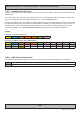
It is expected that you already have knowledge on how to send, receive and interpret the commands by having
studied the examples prior to the "MCC" command table below. The list below is a compressed version of the HEX
values you need to send and will apply to all units (ADDR set as "FF"). For readability the prex "0x" has been
removed in the table and seen as a complete HEX string as values from 00 to FF (2 by 2 letters). Every command will
contain the "MCC" (0x4D, 0x43, 0x43) ASCII letters as default indicator.
The functional byte positions in the table below are indicated with Red Color. The counting of values (xx,yy) should
always be sent as HEX, not numerical values, which means 64 is not 64 in numerical, but rather 100 as numerical.
The single byte that represent MCC Command ID is marked with Green Color. The checksum is marked with Blue
Color. The other byte positions in Black Color are dened as in the "Message Format" seen in the beginning of this
chapter.
NOTE: Due to rmware revisions, some commands listed below will not be available on earlier units.
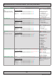
MCC Command Syntax and Functionality Details and Values
Brightness Control
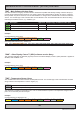
Syntax : 07 FF 4D 43 43 03 23 81 xx yy zz
Function Examples:
Example "50" : 07 FF 4D 43 43 03 23 81 35 30 19
Query "?" : 07 FF 4D 43 43 02 24 81 3F 3F
Reset "R" : 07 FF 4D 43 43 02 24 81 52 2C
Reset "r" : 07 FF 4D 43 43 02 24 81 72 0C
Increase "+" : 07 FF 4D 43 43 02 24 81 2B 53
Decrease "-" : 07 FF 4D 43 43 02 24 81 2D 51
Where xx = "0" to "6"
Where yy = "0" to "F"
Where zz = Calculated Checksum
Max Range: "0" "0" to "6" "4"
Default: "3" "2"
Contrast Control
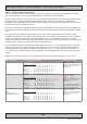
Syntax : 07 FF 4D 43 43 04 22 82 ww xx yy zz
Function Examples:
Example "A50" : 07 FF 4D 43 43 04 22 82 41 35 30 D7
Example "a50" : 07 FF 4D 43 43 04 22 82 61 35 30 B7
Query "?" : 07 FF 4D 43 43 03 23 82 41 FD
Reset "R" : 07 FF 4D 43 43 03 23 82 52 EA
Reset "r" : 07 FF 4D 43 43 03 23 82 72 CA
Increase "+" : 07 FF 4D 43 43 02 24 82 2B 52
Decrease "-" : 07 FF 4D 43 43 02 24 82 2D 50
Where ww = "a" or "A"
Where xx = "0" to "6"
Where yy = "0" to "F"
Where zz = Calculated Checksum
Max Range: "0" "0" to "6" "4"
Default: "3" "2"
"a" / "A" denition is by default
applicable to all signal inputs, not
only the one currently active.
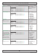
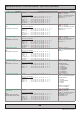
Saturation Control
Note:
In video mode only
Not available on STD units.
Syntax : 07 FF 4D 43 43 03 23 83 xx yy zz
Function Examples:
Example "50" : 07 FF 4D 43 43 03 23 83 35 30 17
Query "?" : 07 FF 4D 43 43 02 24 83 3F 3D
Reset "R" : 07 FF 4D 43 43 02 24 83 52 2A
Reset "r" : 07 FF 4D 43 43 02 24 83 72 0A
Increase "+" : 07 FF 4D 43 43 02 24 83 2B 51
Decrease "-" : 07 FF 4D 43 43 02 24 83 2D 4F
Where xx = "0" to "6"
Where yy = "0" to "F"
Where zz = Calculated Checksum
Max Range: "0" "0" to "6" "4"
Default: "3" "2"