USER MANUAL HM C01 - Compact Rugged Naval Computer HM C01 xxy-zzzz xx = standard or custom y = operating system zzzz = configuration dependent User Manual HM C01 Updated: 05 Nov 2014 Doc Id: INB10042-3 (Rev 8) Created: 363 Approved: 6987 Please visit www.hatteland-display.com for the latest electronic version of this manual. Hatteland Display AS, Åmsosen, N-5578 Nedre Vats, Norway Tel: (+47) 4814 2200 - mail@hatteland-display.com - www.hatteland-display.
Copyright © 2014 Hatteland Display AS Aamsosen, N-5578 Nedre Vats, Norway. All rights are reserved by Hatteland Display AS. This information may not, in whole or in part, be copied, photocopied, reproduced, translated or reduced to any electronic medium or machinereadable form without the prior written consent of Hatteland Display AS. Review also: www.hatteland-display.com/pdf/misc/doc100703-1_permission_to_create_user_manuals.
Contents Contents..................................................................................... 3 Contents of package...........................................................................5 General....................................................................................... 7 About this manual................................................................................8 About Hatteland Display......................................................................8 www.
Contents Specifications.......................................................................... 33 Specifications - HM C01....................................................................34 Technical Drawings................................................................. 35 Technical Drawings - HM C01........................................................... 36 Technical Drawings - Accessories......................................... 37 Technical Drawings - 19” Rack Kit 4U.........................
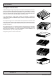
Contents of package This product is shipped with: Item Description 1 pcs of power cable European Type F “Schuko” to IEC. Length 1.8m Illustration EUR TYPE F IEC Note: Only applicable for factory delivered units with AC Power Input FS-CABLE EU 1 pcs of power cable US Type B plug to IEC. Length 1.8m US TYPE B IEC Note: Only applicable for factory delivered units with AC Power Input 80099 1 pcs of DC Power Input housing with internal cable screw terminal.
This page left intentionally blank 6
General 7
Hatteland Display AS About this manual The manual contains electrical, mechanical and input/output signal specifications. All specifications in this manual, due to manufacturing, new revisions and approvals, are subject to change without notice. However, the last update and revision of this manual are shown both on the frontpage and also in the “Revision History” chapter at the end of the manual.
Computers Computers introduction Hatteland Display’s range of type-approved computers is designed to perform in harsh environments while providing the performance and flexibility you expect. We offer rack mount and black box/standalone computer solutions for every need. Our computers are used by system integrators, boat builders and endusers and can be found on all vessel types, all over the world.
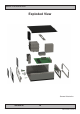
Basic Construction Exploded View General illustration General IND100077-81 10
Product Labels (Examples) Serial Number Label Placement (external) Serial Number Label Layout Product Type Manufacturer & Country Input Voltage & Power Rating Manufactured Date yyyymmdd Barcode (TYP+SNO) Product Hardware Revision Label Size: 6cm x 2cm Serial Number Label Nomenclature AA XXX AAA-AXXX-XXXXXX HT C01 STD-A111-000005 || ||| ||| |||| |||||| || ||| ||| |||| ¤----|| ||| ||| |¤¤¤------|| ||| ||| ¤---------|| ||| ||¤-----------|| ||| ¤¤------------|| ||¤---------------|| |¤----------------|| ¤-
Product Labels (Examples) Operating System Serial Number Label Placement (internal) Please review the “General Installation Recommendations” chapter in this manual before proceeding. Unscrew the 3 chassis screws (FIG 1), and slide the cover slightly (5mm/0.20”) (FIG 2) and lift the cover to reveal the label (FIG 3).
Installation 13
General Installation Recommendations Installation and mounting of computers 1. Units may be intended for various methods of installation or mounting (rack mounting, panel mounting, bracket mounting, ceiling/wall mounting); for details, please see the relevant mechanical drawings. 2. Adequate ventilation is a necessary prerequisite for the life of the unit. The air inlet and outlet openings must definitely be kept clear; coverings which restrict ventilation are not permissible.
General Installation Recommendations Cables Use only high quality shielded signal cables. For RGB/DVI cables use only cables with separate coax for Red, Green and Blue. Configuring DC power input housing connector Note: Only applicable for certain models! For installations that require DC power input, use the provided 2-pin DC Power Input housing with internal cable screw terminal.
General Installation Recommendations CAUTION This unit contains electrostatic sensitive devices. Observe precautions for handling. Computer Upgrade Precaution Note Users who needs to open the computer to change PCI cards, install more memory, or set internal jumpers can do so without voiding the warranty. Before opening a unit’s housing to remove or touch a board, proper ESD measurements must be taken! 1. Operator should ground himself by using a wrist band. 2.
General Installation Recommendations Ferrites The ferrites prevent high frequency electrical noise (radio frequency interference) from exiting or entering the equipment. You can locate the loose ferrites (where applicable, check Contents of Package chapter in the user manual) in the Accessories box which are part of the main computer unit packaging. Some products have also factory mounted ferrites on internal connectors (where applicable).
General Installation Recommendations Cabinet cover removal Note: Areas of interest are marked in this section with arrows in RED color. Please disconnect ALL cables from the computer unit before proceeding! 1: Unscrew 3 screws in rear of cabinet. Turn anti-clockwise using your fingers. 2: Push cover gently down while pushing forward approx 5mm [0.20”] away from the front and then lift the cover. 3: Lift the cover up with both hands. Repeat the procedure backwards to finalize operation.
General Installation Recommendations PCI Card removal / replacement - Introduction Note: Areas of interest are marked in this section with circles and arrows in RED color. Please disconnect ALL cables from the computer unit before proceeding! 1: Unscrew 4 screws on each side of the bracket. Turn anti-clockwise using a Pozidriv #2 screwdriver. 2: Push each side of the bracket, one forward and one backwards in a 45 degree rotation clockwise to slide it out of the tracks.
General Installation Recommendations PCI Card removal / replacement - Half Lenght & Full Height Note: Areas of interest are marked in this section with circles and arrows in RED color. Please disconnect ALL cables from the computer unit before proceeding! 1: Place the PCI Half Length bracket as shown and push/slide it in so it reaches the end of the PCI card. 2: Mount 2 screws on top to fasten the PCI Half Length bracket. Turn clockwise using a Pozidriv #2 screwdriver.
General Installation Recommendations Hard Drive (HDD) removal / replacement Note: Areas of interest are marked in this section with circles and arrows in RED color. Please disconnect ALL cables from the computer unit and HDD’s before proceeding! Note: Illustration shows AC model. For DC models, the power supply must also be removed in order to gain easy access to the HDD. As of June 2011, DC illustration is pending for this page. Meanwhile, please visit http://www.hatteland-display.
General Installation Recommendations DVD/CD Drive removal / replacement Note: Areas of interest are marked in this section with circles and arrows in RED color. Please disconnect ALL cables from the computer unit and DVD/CD drive before proceeding! 1: Unscrew 1 screw on the DVD/CD bracket. Turn anti-clockwise using your fingers. 2: Gently pull out the DVD/CD bracket away. Remember it’s orientation and placement. 3: Unscrew 1 screw on the back of the DVD/CD drive. Turn anti-clockwise using fingers.
General Installation Recommendations Air Filter removal / replacement - Alternative #1 Note: Areas of interest are marked in this section with circles and arrows in RED color. Please disconnect ALL cables from the computer unit and cards before proceeding! 1: Unscrew 4 screws from the fan/filter cover in front of the unit. Turn anti-clockwise using a Pozidriv #2 screwdriver. 2: Gently pull out the fan/filter cover. 3: Gently pull out the Air Filter. Either clean or replace it.
General Installation Recommendations Air Filter removal / replacement - Alternative #2 Note: Areas of interest are marked in this section with circles and arrows in RED color. Please disconnect ALL cables from the computer unit and cards before proceeding! 1: Remove cabinet cover (see beginning of this chapter). When cabinet cover is off, unscrew 1 screw on top which keeps the Air Filter Bracket in place. Turn anti-clockwise using a Pozidriv #2 screwdriver. 2: Gently pull/slide out the Air Filter Bracket.
General Installation Recommendations Front Fan removal / replacement Note: Areas of interest are marked in this section with circles and arrows in RED color. Please disconnect ALL cables from the computer unit before proceeding! 1: Remove cabinet cover (see beginning of this chapter) When cabinet cover is off, unscrew 4 screws from the 2: Gently pull out the fan/filter cover. fan/filter cover in front of the unit. Turn anti-clockwise using a Pozidriv #2 screwdriver.
General Installation Recommendations Mounting Brackets for Console Mounting Note: The unit comes with mounting brackets and screws for console mounting in the package. Please review specifications and “Technical Drawings - Accessories” chapter in this user manual for additional information. 1: Bottom view showing 4 mounting holes. 2: Mount the brackets with 4 x M6x8. Note: Other/longer screws may damage the computer! Connector Side 3: Bottom view with mounted brackets.
General Installation Recommendations 19 inch Rack Kit 4U Note: The unit can also be mounted inside a Hatteland Display 4U cabinet for rack mounting purposes. Please review specifications and “Technical Drawings - Accessories” chapter in this user manual for additional information. 1: Empty 4U cabinet suitable for the computer and final solution (note that there is no 4U top cover) 2: Showing mounting and screw (included) positions.
Physical Connections Front area of computer USB 1,2 12cm FAN intake+filter Power Button Power LED Reset Button DVD/CD Drive HDD LED USB1,2 INPUT/OUTPUT: Supports any USB1.1 (12Mbps) or USB2.0 (480Mbps) compliant peripherals. Drivers for most USB devices are usually included in operating system or on separate installation CD’s delivered with Third Party products. USB 1.1 devices will operate in USB 1.1 mode (12 Mbps).
Physical Connections Connector area of computer Power Input DC Power Input AC Option Connector COM1,2 USB 7,8 PCIe X16 (add2) PCI PCI LPT USB 9,10 PCIe X1 Network GBLAN Keyboard Port Mouse Port VGA RGB DVI-I USB 3,4,5,6 Mic In, Line Out, Audio Line In Power INPUT: (For units supporting AC input) The internal AC power module supports both 115VAC/60Hz and 230/50Hz power input using a standard IEC European power plug. See specifications for more information.
Physical Connections LPT1 Parallel Port INPUT/OUTPUT: Standard LPT1 Printer/Parallel (SPP/EPP/ECP) port using a D-SUB 25P Female connector. Fasten the cable to the connector using the provided screws on the cable housing itself. PS/2 Mouse and PS/2 Keyboard INPUTS: Connect the PS/2 mouse cable to the PS/2 5P Connector (female) marked with MS. Connect the PS/2 keyboard cable to the PS/2 5P Connector (female) marked with KB.
Physical Connections PCIe X16 (add2) Slot: Supports Full Height and Full Length Profile card in one available slot. Cards is normally installed from factory. Please review the General Installation Recommendations chapter in this manual for more information. Additionally consult the 3rd party manual available on the attached documentation CD delivered with this unit. PCIe X1 Slot: Supports Full Height and Full Length Profile card in one available slot. Cards is normally installed from factory.
This page left intentionally blank 32
Specifications 33
Specifications - HM C01 SPECIFICATIONS Note: All specifications are subject to change without prior notice! Please visit www.hatteland-display.com for the latest electronic version. TECHNICAL DESCRIPTION External Connector Type: Computer Specifications: • • • • • • Installed Operating System : None for standard version (check Accessories / Options below for OS options) Media Drive : 1 x DVD-RW/CD-RW Dual Recorder/Player Processor : 1 x Intel® Core™2 Duo Desktop Processor E8400 - 3.
Technical Drawings 35
This document is the property of Hatteland Display AS. This document and any authorized reproduction thereof, must not be used in any way against the interest of Hatteland Display AS. Any authorized reproduction, in whole or in part, must include this legend. Hatteland Display Proprietary information. Not to be distributed to any third party without written permission. Dimensions might be shown with or without decimals and indicated as mm [inches]. Tolerance on drawings is +/- 1mm.
Technical Drawings - Accessories 37
This document is the property of Hatteland Display AS. This document and any authorized reproduction thereof, must not be used in any way against the interest of Hatteland Display AS. Any authorized reproduction, in whole or in part, must include this legend. Hatteland Display Proprietary information. Not to be distributed to any third party without written permission. Dimensions might be shown with or without decimals and indicated as mm [inches]. Tolerance on drawings is +/- 1mm.
This document is the property of Hatteland Display AS. This document and any authorized reproduction thereof, must not be used in any way against the interest of Hatteland Display AS. Any authorized reproduction, in whole or in part, must include this legend. Hatteland Display Proprietary information. Not to be distributed to any third party without written permission. Dimensions might be shown with or without decimals and indicated as mm [inches]. Tolerance on drawings is +/- 1mm.
This document is the property of Hatteland Display AS. This document and any authorized reproduction thereof, must not be used in any way against the interest of Hatteland Display AS. Any authorized reproduction, in whole or in part, must include this legend. Hatteland Display Proprietary information. Not to be distributed to any third party without written permission. Dimensions might be shown with or without decimals and indicated as mm [inches]. Tolerance on drawings is +/- 1mm.
Appendixes 41
Pinout Assignments - Common Connectors Connectors illustrated here are either standard by factory default or may be available (through factory customization). Note that some combinations may not be possible due to space restrictions. List also valid for customized models. All pin out assignments are seen from users Point of View (POV) while looking straight at the connector.
Pinout Assignments - Common Connectors 25-pin Female Parallel (Optional for selected computers) 13 12 11 10 9 8 7 6 5 4 3 2 1 25 24 23 22 21 20 19 18 17 16 15 14 Pin 01 Pin 02 Pin 03 Pin 04 Pin 05 Pin 06 Pin 07 Pin 08 Pin 09 Pin 10 Pin 11 Pin 12 Pin 13 Pin 14 Pin 15 Pin 16 Pin 17 Pin 18 Pin 19 Pin 20 Pin 21 Pin 22 Pin 23 Pin 24 Pin 25 STROBE DATA0 DATA1 DATA2 DATA3 DATA4 DATA5 DATA6 DATA7 ACK BUSY PE SELECT AUTO FEED ERR# INIT# SLIN# GND GND GND GND GND GND GND GND This signal indicates to the printer th
Trouble-shooting GENERAL TROUBLE-SHOOTING CD-ROM FAILURE OR READ/DETECTION PROBLEMS? If the product are operated/located in a area with extreme condensation, the CD/DVD-ROM drive may not work correctly due to condensation on the read head. Keep the product on for a while until it’s reached normal operating temperature, and retry accessing discs. Otherwise, consider using USB memory sticks or alternative storage devices.
Declaration of Conformity We, manufacturer, Hatteland Display AS, Åmsosen, N-5578 Nedre Vats, Norway declare under our sole responsibility that the JH MMD, JH MMC, JH STD, JH MIL, HM NMD, HM MIL, HM CMD, HT STD, HD MMD, HM MMD, HT MMC, HD MMC and HT (computers) product ranges is in conformity with the following standards in accordance with the EMC Directive. Low Voltage Directive 2006/95/EC EN 60950:2006/A2:2013 EMC Directive 2004/108/EC EN 55022:2010 / AC:2011 Class A EN 55024:2010 Signature:..............
Return Of Goods Information Return of goods: (Applies not to warranty/normal service/repair of products) Hatteland Display referenced as “manufacturer” in this document. Before returning goods, please contact your system supplier before sending anything directly to manufacturer. When you return products after loan, test, evaulation or products subject for credit, you must ensure that all accessories received from our warehouse is returned.
Terms Terms Of Sale And Delivery 1) APPLICATION The terms of sale and delivery apply for Hatteland Display. 2) PRICE a) The price is per each, if nothing else has been stated, VAT not included. Price is based on the prices from our suppliers, current custom rates, taxes, rate of exchange and international raw material prices. We reserve ourselves the rights to adjustments in case of alternation on the above mentioned. b) Included in the price is the supplier’s standard packing.
Terms 12) CANCELLATION / RETURN Binding sales contract is concluded when we have confirmed customer’s purchase order. Any disagreements in our order confirmation must be reported to seller within 6 days. The agreement can not be altered without our permission, after acceptance from our supplier. If goods are wanted to be returned, a Return No must be assigned from seller. Returned goods without a Return No will not be accepted. By return of stock listed goods, 20% return fee is charged.
Notes General Notes: - License Terms for the installed OEM Operating System (OS) can be found in the following default factory paths: Note: This is a general listing for a varity of OS’s Hatteland Display can factory install depending on unit. Please check specification for your unit to verify type of OS installed in order to retrieve the license terms. Microsoft® Windows® 7 Professional: C:\Windows\System32\en-US\Licenses\_Default\Professional\license.
User Notes Appendix IND100077-24 50
Revision History Please note that references to page numbers may only be valid for the latest revision. Rev. By Date 1 JE SE 29 Mar 2011 1st release Notes 2 SE 08 Apr 2011 Minor text changes throughout manual. Release for internet.
w ww.hat tel and-di sp l ay .