
Owner manual


ASSEMBLY INSTRUCTIONS FOR
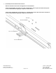
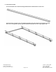
C-10, C-11 & C-12 SERIES RACKS
C12S-1 with 26” Legs shown above.
Package Contents:
HARDWARE KIT PARTS
(8) 3/8”-16 x 3” CARRAIGE BOLTS (1) RAIL DRIVER’S SIDE ASSEMBLIES
(20) 3/8”-16 x 2” CARRAIGE BOLTS (1) RAIL PASSENGER’S ASSEMBLIES
(4) 3/8”-16 x 1-3/4” CARRAIGE BOLTS (1) FRONT RECTANGLULAR CROSSBAR
(12) 3/8”-16 x 1-3/4” HEX BOLTS (1) MIDDLE CROSSBAR ASSEMBLY
(4) 3/8”-16 x 1-1/2” HEX BOLTS (1) REAR CROSSBAR
(4) 3/8”-16 x 1-1/4” HEX BOLTS (4) LEGS
(4) 3/8” x 1-1/4” LAG BOLTS (4) CAMPER FEET
(52) 3/8”-16 NUTS (4) HD BRACES
(
52
)
3/8” SPLIT LOCK WASHERS
(
2
)
EXTENDED CAB BRACES & HARDWARE
(
EX VERSION ONLY
)
Before you begin:
Remove all components from the shipping carton.
The rack should be assembled on a padded surface such as carpet to prevent scratching of aluminum surfaces. Remove bands
securing components together.
Read the instructions thoroughly to familiarize yourself with the assembly sequence.
Note that you DO NOT tighten any nuts and bolts until the completed rack is installed on the vehicle unless specified. This allows for
minor adjustments to the rack during the installation process.
Gather the following tools used to assemble and install the rack.
9/16” Socket or open end wrench
3/8” Drill bit and drill
Pencil or marker
Tape measure
Center punch and hammer (optional)
Level (optional)
2 Clamps (optional)
Boards (optional)
HAULER RACKS, INC. Toll Free: 1-800-843-5445
7109 31
st
Avenue North Phone: 763-546-5620
Minneapolis, MN 55427-2848 Fax: 763-546-0933
Page 1 of 14 WWW.HAULERRACKS.COM