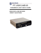
PT-VIDEO-MDVR Installation and Users Guide MOBILE DIGITAL VIDEO RECORDER COMPACT FLASH STORAGE
CONTACT INFORMATION: TECHNICAL SUPPORT AND SERVICE HAVIS-SHIELDS EQUIPMENT CORPORATION 75 JACKSONVILLE ROAD WARMINSTER, PA. 18974 TOLL FREE: (800) 524-9900 DIRECT: (215) 957-0720 FAX: (215) 957-0729 ENFORCEMENT TECHNOLOGIES INTERNATIONAL, LLC 1932 SHORTER AVE. , ROME, GA.
WARNINGS AND CAUTIONS TO REDUCE THE RISK OF FIRE OR ELECTRIC SHOCK, DO NOT EXPOSE THIS PRODUCT TO RAIN OR MOISTURE. DO NOT INSERT ANY METALLIC OBJECTS THROUGH THE VENTILATION GRILLS OR OTHER OPENINGS ON THE EQUIPMENT.
IMPORTANT SAFEGUARDS 1. READ AND RETAIN INSTRUCTIONS Read the instruction manual before operating the equipment. Retain the manual for future reference. 2. CLEANING Turn the unit off and unplug from the power outlet before cleaning. Use a damp cloth for cleaning. Do not use harsh cleansers or aerosol cleaners. 3. ATTACHMENTS Do not use attachments unless recommended by manufactured as they may affect the functionality of the unit and result in the risk of fire, electric shock or injury. 4.
13. DAMAGE REQUIRING SERVICE Unplug the equipment from the wall outlet and refer servicing to qualified service personnel under the following conditions: A. B. C. D. E. F. When the power supply cord or the plug has been damaged. If liquid has spilled or objects have fallen into the unit. If the equipment has been exposed to water or other liquids. If the equipment does not operate normally by following the operating instructions, adjust only those controls that are covered by the operating instructions.
MOBILE DIGITAL RECORDER FEATURES The Mobile Digital Recorder is a true VCR replacement with advanced features that take it beyond the standard VCR. The digital recorder features one video and two audio inputs and one video /audio output. The DVR operates as a simplex recorder offering up to 640 x 240 resolution recording at 30 frames/sec and simultaneous dual channel audio recording. The recorder may also be used in a time-lapse mode for recording frame rate up to 1 frame every 8 seconds.
The small mechanical size allows several recorders to fit in the space of an existing VCR or allow the unit to be mounted in a standard automotive DIN format. • • • • • • • • • • • • • • • 2 True low cost VCR replacement with no moving parts, no internal fan, no audible noise. Unparalleled Search capability with up to 98x Fast Forward Review. Optional integrated GPS position and speed tracking and recording. Recording of the GPS speed, position and time attached to a video frame.
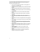
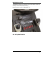
MDVR INSTALLATION The MDVR features dual captured nuts in both sides of the unit allowing console faceplate mounting.
MDVR IGNITTION / POWER ON CONNECTION MDVR Ignition Trigger Power ON Control The MDVR features an auto power on and begin to record function on the “ignition trigger”. When this trigger goes high, the DVR will turn on and begin to begin recording. If the Power Button on the front of the unit is hit, the unit will turn off, but then read the “ignition trigger” and turn back on. This is a “ignition trigger” priority unit.
MDVR main Harness wire connections (25-pin connector) Red – Power (direct 12 volt positive) Black – Ground (12 volt negative) Yellow – Ignition (switched 12 volt positive) Green – Trigger 1 Orange – Trigger 2 Brown – Trigger 3 Blue – Trigger 4 Gray – Trigger 5 NOTE 1: Trigger connections are pre-set (default) to activate on positive Switching. They can be changed to negative switching by changing MDVR settings in trigger Menu.
NOTE 3: In order to view programmable settings on PT-VIDEO monitor, you must use adaptor cables provided to connect MDVR video out to number 2, 3 or 4 camera inputs on the monitor. (Cannot connect to camera 1 input.). *** If you have a four-camera system (PT-VIDEO-4) you must temporarily disconnect one of the cameras and attach the MDVR video out cable in order to view the recorder settings and data. After MDVR settings are confirmed, the camera must be reconnected.
DIGITAL RECORDER FRONT PANEL OPERATION The DVR features an illuminated keypad for easy operation in dark environments. Below is a description of the functions of the Digital Recorder front panel buttons. Some buttons will have different functions depending upon if the recorder is recording, stopped, or playing back video. Figure 2: Front Panel Controls Power Button: The unit is typically powered on by the Ignition trigger, but may alternately be powered on by pressing the Power Button.
Left Arrow Key (mode dependant): Pause & Playback Mode: Left Arrow Key adjusts fast reverse playback speed up to 90x. Right Arrow Key (mode dependant): Pause Mode: Right Arrow Key adjusts the slow forward playback speed from paused to 0.5x speed. Playback Mode: Right Arrow Key adjusts fast forward playback speed up to 90x. Up Arrow Key (mode dependant): Playback Mode: During standard 1x playback, Up Arrow Key selects audio channel 1 to be output.
BASIC MDVR OPERATION The OSD shown in Figure 5 below is the basic OSD for the Record, Live View and Playback Modes of operation. The video is recorded without these overlays, but the data shown is attached to each video frame as Meta data for extraction by the video player software. Time & Date: This time and date is either entered manually and kept current with by the MDVR or is acquired and synchronized by the GPS unit if the option is selected.
Figure 3: Basic OSD MDVR MENU STRUCTURE MDVR Video Search Menu The OSD shown in Figure 5 below is the video search menu used for searching recorded video files on the Compact Flash card. The column on the left shows the days with the column on the right showing time in that day. A pound symbol in the right column signals that record was triggered by an event.
Figure 4: Recording Search Menu MDVR Main Menu The OSD shown in Figure 8 below is the main unit menu. From this menu access to all other setup screens is possible.
MDVR Setup Menu Setup Menu (Figure 9) Field Units Action Selection of English or Metric units. Default English Video Dwell Time Selects the time between video switches. 0 seconds will allow a trigger position to determine camera input selected. 0 sec Time Setup Password Setup Advanced Setup Brings up the Time Setup menu.
Date Time Daylight Savings Figure 7: System date (assuming GPS date is OFF) System time (assuming GPS time is OFF) Automatic adjustment for daylight savings time change. Today’s Date Today’s Time ON Time Setup Menu Advanced Setup Menu (Figure 11) Field Restore Defaults Erase Media Menu Password Action Restores the factory default settings. Permanently deletes all recorded data from the selected media. Sets the password field or no password for the menu.
System Name Trigger x Figure 8: 14 character name (i.e. Car # / Officer / Other) 1 character trigger name MDVR-CF 1-6 Titles Setup Menu Trigger Setup (Figure 15) Field Trigger 1-6 Speed Action Enter a name for the trigger event / Enter if the trigger is active high or low / Select the action for the trigger event (MARK EVENT, START RECORD, STOP RECORD, RECORD while active, SWITCH CAMERA, STEALTH REC, DISPLAY ONLY) Enable recording at a given input speed.
o o o o o START RECORD: Starts a recording and will record until the stop button is pushed on the front of the unit or the storage media is full. STOP RECORD: Stops a recording if the unit is recording. RECORD: Starts a recording and records while the trigger is active. Stops recording when the trigger is not active. SWITCH CAMERA: Switches the camera input to the unit based on the settings in the Setup Menu.
Frame Rate Audio Recording Priority Prompt Total Time Figure 10: image quality provides longer record time at lower video quality. Selects the frame rate from 30 FPS down to 1/8 FPS. Selects whether to record 2 channels of audio (ON), one channel associated with the video being recorded (SWITCHED) or no audio (OFF). ON / OFF: Selects whether to prioritize the recorded video. See Figure 6 Displays the recording time capacity based on the Compact Flash card size and record settings above.
GPS Data Format Selects GPS display format: DDD:MM:SS, DDD:MM.mm, DDD.dddd Figure 11: GPS Setup Menu System Info DDD:MM:SS (Figure 18) Field Disk Capacity Percent Used Percent Free Firmware Version Figure 12: Action Storage capacity of the record media. Percentage of used space on the record media. Percentage of free space on the record media. Version of the installed firmware.
MDVR Password Menus The menus shown in Figure 19 below allow for configuration of the units password access. All buttons on the front of the unit may be used for password access EXCEPT THE POWER BUTTON. The password field consists of 6 characters with a default password of: “Left Arrow”, “Right Arrow”, “Left Arrow”, “Right Arrow”, “Left Arrow”, “Right Arrow”. After this sequence is entered, the system allows access for 30 minutes (or after cycle power) before the password is enabled again.
COMPACT FLASH FILE STRUCTURE In the root directory of the Compact Flash card, the DVR will create a new subdirectory for each day of recording. The subdirectory is named as follows: Mmm.dd.yyyy Mmm = 3 letter month abbreviation, e.g. Jan, Feb, Mar, ... Dec dd = day (01 - 31) yyyy = 4 digit year, e.g. 2006 Each subdirectory will contain one or more AVI files named as follows: ssssssssssssss_Mmm.dd.yyyy_hh.mm.ss.avi sss.. = User defined system name. This name can be from 0 to 14 characters in length.
BACK PANEL CONNECTIONS Main Interface Connector 25-pin DSUB Pin # Function 1 Record LED Out; 3.3V with a 1k series resistor. 2 3 12V Camera Output Trigger In 1 5 6 7 8 9 10 Trigger In 2 Remote power on / Ignition Trigger In 3 Trigger In 4 Trigger 5 AUX 12V Output w/ 100ohm series resistor. Trigger 6 / Mic Trigger In on 8-pin Molex. 11 14 15-16 4, 12, 13, 17,18, 25 19 20 21 20 Spike protected Automotive Power Output.
22 23 24 25 RS232-TX 3 RS232-RX Radar IF RS232-TX Radar IF Ground Notes: 1. Pins 23 & 24 are dedicated to the Radar Interface Only. 2. Pin 11, Trigger 6 / Mic Trigger Input are also connected to pin 4 of the 8-pin Molex. Use only one or the other. 3. Pin 14 is protected automotive output power which could range from 10V to 26V.
EQUIPMENT SPECIFICATIONS Specifications Recording Capabilities Meta-Data Capture for Each Frame NTSC video camera input up to 30 fps with synchronized audio and meta-data. Input voltage, unit temperature, 14 character unit name, panic button events, all triggers status and names, operating mode & version numbers, time & date, optional GPS lat/long/speed. Compression Motion JPEG compression w/ 5 selectable compression ratios. Selectable 640 x 240 or 320 x 240. Selectable 30 FPS to 1/8 FPS.