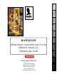
Introduction Table of Contents Warranty HAWKJAW Specification Ordering Installation Instructions Sheet OPERATION, MAINTENANCE AND SERVICE MANUAL Operation MODEL 65K-2GJR Maintenance & Repair Serial 10 - 20 Serial# #21-22 Drawings 1245 East 23rd Street Long Beach, CA 90806 Phone: 562-424-0709 Fax: 562-490-9959 www.hawkindustries.com Trouble Shooting HAWK INDUSTRIES, INC.
Introduction Hawk's design philosophy is simple: Design with the end user in mind. Make it tough, dependable and easy to maintain. Hawk has designed the HawkJaw with this same simple formula. FEATURES The HawkJaw 65K-2GJR is a hanging unit that will spin, make up and break out drill pipe. It is revolutionary because the tool spins and makes up drill pipe or breaks out and spins drill pipe in 12 seconds or less. A patented self-energized grip system provides consistent torque values to the drill string.
Table of Contents 2 3 6 7 8 9 9 HawkJaw Location Hanging Cable Requirements Hydraulic Requirements Air Requirements Raise/Lower Cylinder Hook - Up Operation Start-up Procedure Adjusting the Wrenches Adjust for Make Up Adjusting the Spinner Adjust for Make Up Rest Position Adjust Spinner for Make Up (cont.) Position for Make Up Setting Make Up Torque Make Up Adjusting the Wrenches Adjust for Break Out Adjusting the Spinner Adjust for Break Out Rest Position Adjust Spinner for Break Out (cont.
Table of Contents (cont.
Table of Contents (cont.
Warranty HAWKJAW 65K-2GJR STANDARD WARRANTY AND FIELD SERVICE Your Hawkjaw must be free of material and workmanship defects for a period of six months from the date of delivery. If any items fail because of a manufacturing defect within that period of time, that item will be replaced by Hawk Industries. Hawk Industries at its discretion may extend this warranty period. Replacement of parts will be accomplished either at the factory or at a designated service point.
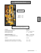
Specification Sheet DIMENSIONS Specification Sheet DEPTH: 34 in. WIDTH: 40 in. HEIGHT: 90 in. PERFORMANCE AND POWER REQUIREMENTS TORQUE: MAXIMUM PIPE ROTATION: WRENCH SIZE RANGE: SPINNER SIZE RANGE: 65,000 ft. lbs. 50 degrees 3 1/2" __ 8" OD tool joints 3" __ 5 1/2" OD tube AIR POWER SOURCE: HYDRAULIC POWER SOURCE: HYDRAULIC POWER SOURCE TYPE: 100 psi @ 2-10 cfm 2,500 psi @ 20-35 gpm Closed Center System WEIGHT: 2,630 lbs.
Ordering Instructions All parts must be ordered by giving the quantity needed, the full part number as listed in this manual under Part #, the unit serial number, the model number and part name.
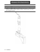
Installation Hanging Cable Location 1. Anchor the hanging cable to a point as close to the derrick crown as possible. The longer the hanging cable, the easier the HawkJaw is to move on and off the drill pipe. 2. Locate the cable hang point as high above the center of the rotary table as possible. The cable must hang within 2'-4' ft. of the rotary table center.
Hanging Cable Requirements 1. 2. 3. 4. 5/8" diameter steel cable. Appropriate hanging cable hardware for 5/8" diameter steel cable. Enough cable length to suspend the Hanger Eye (HE) 20' ft. above the rig floor. Enough cable length to allow the HawkJaw to rest on the rig floor 3'- 5' ft. away from the rotary table with the lift cylinder completely stroked out. The lift cylinder is 13' ft. long when completely stroked out.
Hydraulic Requirements 1. Pressure compensated pump set to pressure compensate at 2600 psi. 2. Minimum volume of 20 gpm. 35 gpm for top performance. 3. 1" minimum Pressure line. 1 1/4" Pressure line if the power unit is located more than 100' apart from the HawkJaw. The hose working pressure must be 3000 psi or greater. 4. 1 1/4" minimum Tank line. 500 psi minimum hose working pressure. 5. Hawk approved pressure side non-collapsible on-board 3000 psi filter (HF) (Part # 061H25).
Air Requirements 1. Clean, dry air at 100 psi @ a negligible volume. 2. On board auto-dump air filter (AF) (part# 061-A22), located on board the rear of the Hawkjaw. 3. Enough slack in the line for the HawkJaw to move from its rest position to the drill pipe connection to the mouse hole connection. WARNING The HawkJaw must receive clean, dry air. Running the HawkJaw without a Hawk approved air filter (AF) voids the warranty and shortens component life.
Raise/Lower Cylinder Hook - Up 1. Use the Raise/Lower cylinder Cap side Bolt (B) to connect the HawkJaw Suspension Ring (SR) to the Raise/Lower cylinder (C). 2. Use the Raise/Lower cylinder Cap side Lock Nut (N) to secure the Raise/Lower cylinder Cap side Bolt (B). 3. Connect the Hanger Eye (HE) to the hanging cable. 4. Connect the HawkJaw Rod side (HR) and Cap side (HC) hydraulic Leader hoses to the Raise/Lower cylinder Rod side (RR) and Cap side (RC) hoses. NOTE NOTE Tightly connect the hose fittings.
Start-up Procedure 1. Connect the air power source with the Air (A) line. 2. Make sure the hydraulic reservoir is full. 3. Connect the hydraulic Pressure (P), Tank (T) and Air (A) lines. "P" and "T" Port Designations are stamped on the Main Hydraulic Manifold (M). Do not hook up the hoses backward 4. Check for hydraulic leaks. NOTE Tightly connect the hose fittings. A loose connection causes a pressure drop in the hydraulic fluid which heats up the fluid and reduces component life.
Adjust for Make Up NL Adjusting the Wrenches 1. Make sure the nut lock (NL) is in the unlocked position. Adjusting the Nut Lock Detent Setting (If Needed) A. Loosen the jam nut (J) to allow some space for the arm to adjust. B. Screw the arm (A) in or out to adjust the stiffness of the springloaded detent (SD). C. Tighten the jam nut (J) to secure the arm (A) from loosening. Part Number Part Name Adjust Nut Locking System Operation SD J A Part # 061-30280 Continued on next page.
Adjust for Make Up 2. Measure the tool joint with OD calipers. 3. Use the 1 1/2" wrench to adjust the Pointer (P) on the Pipe stop index (PI) to the OD tool joint size. 4. For safety, adjust the Bottom wrench nut (BN) 1" larger than the Top wrench nut (TN) and Middle wrench nut (MN). 5. Rotate the Top wrench nut (TN) and the Middle wrench nut (MN) to the OD tool joint size. Visually align the end face (F) of the wrench nut with the scale (S) on the wrench. 6.
Adjust for Make Up QR Adjusting the Spinner 1. Measure the drill pipe tube with OD calipers. 2. Tube Size Use 4 1/2"- 5 1/2" Front Holes (FH) 3 1/2"- 4" Middle Holes (MH) 2 7/8" Rear Holes (RH) 3. Remove the two quick release pins (QR). 4. Slide the whole Drive unit (D) forward or backward to the appropriate holes. 5. Replace the quick release pins (QR). D MH Operation FH BH 6. Shift spinner directional valve (SDV) fully forward to the make position as shown. Continued on next page.
Adjust Spinner for Make Up (cont.) 7. Use the rotary table to spin drill collars larger than 5 1/2" OD. Place the HawkJaw spinner in the rest position. Rest Position 1. Remove the Spinner Arm Pins (P). 2. Rotate the Spinner back to the Pullback position (R). 3. Insert the Spinner Arm Pins (P) with retainer clips.
Position for Make Up 1. Stab the drill stand. 2. Center the Suspension Ring (SR) on the Lateral tilt screw (LTS). 3. If the HawkJaw rests on the rig floor, use Raise (R) to raise the HawkJaw 1'- 2' ft. off the rig floor. 4. If the HawkJaw is hooked back to the derrick, unhook the HawkJaw. 5. Use the Control Handles (CH) to pull the HawkJaw onto the drill pipe connection. 6. Use Raise (R) and Lower (L) to center the Top wrench dies (TD) and the Middle wrench dies (MD) between the shoulder (S). 7.
Position for Make Up (cont.) TW 9. Check that the HawkJaw Top wrench (TW), Middle wrench (MW) and Bottom wrench (BW) hang straight and level when the drill pipe is against the pipe stop. 10. If the HawkJaw wrenches (TW, MW, BW) hang tilted forward or backward, use the crescent wrench to adjust the Turnbuckle (TB). 11. If the HawkJaw wrenches (TW, MW, BW) hang sloped to the right or to the left, use the Control Handles (CH) to back the HawkJaw off the pipe.
Setting Make Up Torque RN Warning TN RNA When Hawkjaw is at rest, press in the red E-Stop (E) button. Shown set for 30,000 ft. lbs. SS G S T GH Operation 1. Follow the steps on pages 14-21. 2. Use the Red needle adjust (RNA) to rotate the Torque gauge red needle (RN) to the desired torque. 3. Rotate the Torque Set knob (K) counter- clockwise as far as the Torque Set knob (K) will turn. 4. Rotate the Selector Switch (SS) to the make position. 5. Press in the Grip Hold (GH) button. 6.
Make Up 1. Follow the steps on pages 14-21. 2. Press in the Grip Hold (GH) button. 3. Press and hold Spin (S) until the stand rotates down to the shoulder. 4. Release Spin (S). 5. Push in and hold the wrench Grip (G). 6. Push and hold down Torque (T). 7. Watch the Torque gauge needle (TN). 8. When the Torque gauge needle rises above and settles at the desired torque (this rising above is a normal hydraulic adjustment), release Torque (T). Immediately release Torque (T) button and the wrench Grip (G) button.
Adjust for Break Out Adjusting the Wrenches 1. Make sure the nut lock (NL) is in the unlocked position. NL Adjusting the Nut Lock Detent Setting (If Needed) A. Loosen the jam nut (J) to allow some space for the arm to adjust. B. Screw the arm (A) in or out to adjust the stiffness of the springloaded detent (SD). C. Tighten the jam nut (J) to secure the arm (A) from loosening.
Adjust for Break Out 2. Measure the tool joint with OD calipers. 3. Use the 1 1/2" wrench to adjust the Pointer (P) on the Pipe stop index (PI) to the OD tool joint size. 4. For safety, adjust the Top wrench nut (TN) 1" larger than the Bottom wrench nut (BN) and Middle wrench nut (MN). 5. Rotate the Bottom wrench nut (BN) and the Middle wrench nut (MN) to the OD tool joint size. Visually align the end face (F) of the wrench nut with the scale (S) on the wrench. 6.
Adjust for Break Out QR Adjusting the Spinner 1. Measure the drill pipe tube with OD calipers. 2. Tube Size Use 4 1/2"- 5 1/2" Front Holes (FH) 3 1/2"- 4" Middle Holes (MH) 2 7/8" Rear Holes (RH) 3. Remove the two quick release pins (QR). 4. Slide the whole Drive unit (D) forward or backward to the D appropriate holes. 5. Replace the quick release pins (QR). MH Operation FH BH 6. Shift spinner directional valve (SDV) fully back to the make position as shown.
Adjust Spinner for Break Out (cont.) 7. Use the rotary table to spin drill pipe larger than 5 1/2" OD. Place the HawkJaw spinner in the rest position. Rest Position 1. Remove the Spinner Arm Pins (P). 2. Rotate the Spinner back to the Pullback position (R). 3. Insert the Spinner Arm Pins (P) with retainer clips.
Position for Break Out 1. Stab the drill stand. 2. Center the Suspension Ring (SR) on the Lateral tilt screw (LTS). 3. If the HawkJaw rests on the rig floor, use Raise (R) to raise the HawkJaw 1'- 2' ft. off the rig floor. 4. If the HawkJaw is hooked back to the derrick, unhook the HawkJaw. 5. Use the Control Handles (CH) to pull the HawkJaw onto the drill pipe connection. 6. Use Raise (R) and Lower (L) to center the Middle wrench dies (MD) and the Bottom wrench dies (BD) between the shoulder (S). 7.
Position for Break Out (cont.) 9. Check that the HawkJaw Top wrench (TW), Middle wrench (MW) and Bottom wrench (BW) hang straight and level when the drill pipe is against the pipe stop. 10. If the HawkJaw wrenches (TW, MW, BW) hang tilted forward or backward, use the crescent wrench to adjust the Turnbuckle (TB). 11. If the HawkJaw wrenches (TW, MW, BW) hang sloped to the right or to the left, use the Control Handles (CH) to back the HawkJaw off the pipe. Use Lower (L) to lower the HawkJaw to the rig floor.
Break Out 1. Follow the steps on pages 14, 2430. 2. Rotate the Selector Switch (SS) clockwise to the break position. 3. Push in the Grip Hold (GH) button. 4. Push and hold in the wrench Grip (G). 5. Push and hold down Torque (T). 6. When break out occurs, release Torque (T). Immediately release the wrench Grip (G). See note below. 7. Press and hold down Spin (S) until the stand pops out of the connection. Release Spin (S). If the stand will not spin, release Spin (S). Repeat Steps 4-6. 8.
Low Torque Warning Test T CHECK If the Torque cylinder strokes out before the desired torque is reached, the Torque gauge needle (TN) will fall off to approximately a 8000 Ft.Lb. reading. If this happens, release Torque (T). Immediately release Grip (G). Wait for the Torque cylinder to reset. LOW TORQUE WARNING SYSTEM CHECK Test#1: Hawk strongly recommends testing the Low Torque Warning System on every trip. If this test procedure is not performed, the drill string could be over torqued.
Wrench Maintenance D1 Grease Once per Trip D2 Initial Steps 1. Make sure the HawkJaw is off the drill pipe connection and in the rest position on the derrick. 2. Shut down the Hydraulic power unit. 3. Press, push, and pull all control buttons repeatedly to bleed hydraulic pressure. 4. Disconnect the Air power supply. 5. Press, push, and pull all control buttons repeatedly to bleed air pressure. 6. Assume that there is still a load on every actuator. Proceed with caution.
Wrench Maintenance Grease Once per Week Wrench Hook NS N T 1. Surface grease the hook thread (T) on the top wrench, middle wrench, and bottom wrench. 2. Rotate the wrench nut (N) on the top wrench, middle wrench, and bottom wrench to spread grease on the full thread area. Wrench Nut 1. Surface grease the wrench nut surface (NS) on the top wrench, middle wrench, and bottom wrench. Hook Pivot Bearing Cap 1. Pump the Hook pivot bearing cap grease fitting (H) on the top and bottom of each wrench.
Wrench Maintenance Grease Once per Week G2 G1 G3 G4 Initial Steps 1. Make sure the HawkJaw is off the drill pipe connection and in the rest position on the derrick. 2. Shut down the Hydraulic power unit. 3. Press, push, and pull all control buttons repeatedly to bleed hydraulic pressure. 4. Press the E-Stop button on the right control handle. 5. Press the E-Stop button on the right control handle. 6. Assume that there is still a load on every actuator. Proceed with caution.
Wrench Maintenance Grease Once per Month MP2 MP1 Tools Required Grease gun Initial Steps 1. Make sure the HawkJaw is off the drill pipe connection and in the rest position on the derrick. 2. Shut down the Hydraulic power unit. 3. Press, push, and pull all control buttons repeatedly to bleed hydraulic pressure. 4. Press the E-Stop (E) button on the right control handle. 5. Disconnect the Air power supply. 6. Assume that there is still a load on every actuator. Proceed with caution.
Hydraulic Filter Maintenance Change Every 2 Months Initial Steps 1. Depress the Red button (RB) located under the See-through rubber weather cap (SC). 2. Operate the HawkJaw. 3. If the Red button pops up, proceed with Step 4. 4. Make sure the HawkJaw is off the drill pipe connection and in the rest position on the derrick. 5. Shut down the Hydraulic power unit. 6. Press, push, and pull all control buttons repeatedly to bleed hydraulic pressure. 7. Press the E-Stop (E) button on the right control handle. 8.
Air Filter Maintenance Change Every 6 Months Initial Steps CB 1. Disconnect the Air power supply. 2. Bleed Air Pressure. FC S Air Filter 1. Remove the two right Corner bolts (CB). 2. Slide out the Second stage filter cartridge (SC) and Star spacers (S). 3. Slide out the First stage filter cartridge (FC) and Star spacers (S). 4. Slide in the new First stage Filter cartridge and Star spacers (S). 5. Slide in the new Second stage filter cartridge and Star spacers (S). 6.
Changing the Hook Dies B Initial Steps 1. Make sure the HawkJaw is off the drill pipe connection and in the rest position on the derrick. 2. Shut down the Hydraulic power unit. 3. Press, push, and pull all control buttons repeatedly to bleed hydraulic pressure. 4. Press the E-Stop (E) button on the right control handle. 5. Disconnect the Air power supply. 6. Assume that there is still a load on every actuator. Proceed with caution. D Hook Dies DH Maintenance & Repair 1.
Changing the Heel Dies RB B R Initial Steps 1. Make sure the HawkJaw is off the drill pipe connection and in the rest position on the derrick. 2. Shut down the Hydraulic power unit. 3. Press, push, and pull all control buttons repeatedly to bleed hydraulic pressure. 4. Press the E-Stop (E) button on the right control handle. 5. Disconnect the Air power supply. 6. Assume that there is still a load on every actuator. Proceed with caution. Wrench Heel Die 1.
Changing the Heel Dies (cont.) 7. Make sure the back and sides of the new Die are clean. 8. Grease the back of the new Die. 9. Insert the new Die into the Die Holder (DH) with the teeth of the Die facing out. 10. Place the Die Holder (DH) back in the Die Pivot Block (DB). 11. Insert the Heel Die Pin (P). 12. Replace the Heel Die Rollers (R). 13. Replace the Roller Bushings (RB). 14. Use the 3/4" wrench to replace the Heel Die Roller Bolts (B) and Lock Washers.
Spinner Maintenance GH Notice Spinner chain lubrication must be done during normal operation of the Hawkjaw. Do not run the spinner when the Hawkjaw is not on the pipe. Initial Steps 1. Position the Hawkjaw for breakout. Chain Lubrication S CO 1. Pull the Hawkjaw onto the pipe. 2. Press in the Grip Hold (GH) button. 3. Press and hold the Spin (S) button. While holding down the Spin (S) button, press and hold the Chain Oiler (CO) button for 3 seconds. 4. Release the Spin (S) button. 5.
Spinner Maintenance Grease Once per Month G1 G2 Initial Steps 1. Make sure the HawkJaw is off the drill pipe connection and in the rest position on the derrick. 2. Shut down the Hydraulic power unit. 3. Press, push, and pull all control buttons repeatedly to bleed hydraulic pressure. 4. Press the E-Stop (E) button on the right control handle. 5. Disconnect the Air power supply. 6. Assume that there is still a load on every actuator. Proceed with caution.
Spinner Maintenance TC Grease Once per Month Tools Required Grease gun Spinner Grip Cylinders 1. Pump grease fitting SC1-SC2 on the Top spinner grip cylinder (TC) and the Bottom spinner grip cylinder (BC). Chain Drive Shaft Bearing BC 1. Pump grease fitting CB1.
Spinner Maintenance P Grease Once per Month Tools Required Grease gun Spinner Mount Sliding Tube 1. Pump grease fittings ST1-ST4. Check Oil Level Once per Month Lubricant Required # 32 weight gear oil Reducer Gear Box 1. Make sure the gear box oil level reaches the top pipe plug (P). NOTE Consistent lubrication of the Spinner increases performance and component life.
Changing the Spinner Chain Tools Required 7/16" wrench, Hammer, Needle-Nose Pliers Initial Steps 1. Make sure the HawkJaw is off the drill pipe connection and in the rest position on the derrick. 2. Shut down the Hydraulic power unit. 3. Press, push, and pull all control buttons repeatedly to bleed hydraulic pressure. 4. Press the E-Stop (E) button on the right control handle. 5. Disconnect the Air power supply. 6. Assume that there is still a load on every actuator. Proceed with caution. SD QR Chain 1.
Changing the Spinner Chain (cont.) 8. From the front of the unit, use the Needle-nose pliers to remove the Cotter pins (CP) in one of the Chain links. 9. Use the hammer to remove the Chain link pin (CLP). 10. Pull out the old chain. Make sure the chain does not catch on the Drive sprocket (DS). 11. Feed the chain into the spinner behind the Drive Sprocket (DS) until both ends of the new chain meet at the roller sprockets (DRS). 12.
Changing the Drive Rollers Tools Required 3/4" wrench Initial Steps 1. Make sure the HawkJaw is off the drill pipe connection and in the rest position on the derrick. 2. Shut down the Hydraulic power unit. 3. Press, push, and pull all control buttons repeatedly to bleed hydraulic pressure. 4. Press the E-Stop (E) button on the right control handle. 5. Disconnect the Air power supply. 6. Assume that there is still a load on every actuator. Proceed with caution. Drive Rollers 1.
Changing the Drive Rollers 8. Slide in the Drive Roller Sprockets (4) . Make sure the "T" on each Drive Roller Sprocket faces up. 9. Replace the Bearing Caps (2) and Bearing Seals (3). 10. Use the 3/4" wrench to replace all Bearing Cap Bolts (9). Use new Lock Washers (12) and red loctite when replacing the Bearing Cap Bolts (9). Assemble the Lock Washers (12) as shown. Torque Bearing Cap Bolts (9) to 75 lb. ft. Maintenance & Repair Part Numbers WARNING Replace all four Drive Rollers.
Changing the Drive Roller Sprocket Bearings Tools Required Four 1/4"-20 x 1 1/2" Hex Tap SS (Part # 999-805867), 7/16" wrench, 3/ 4" wrench Initial Steps 1. Make sure the HawkJaw is off the drill pipe connection and in the rest position on the derrick. 2. Shut down the Hydraulic power unit. 3. Press, push, and pull all control buttons repeatedly to bleed hydraulic pressure. 4. Press the E-Stop (E) button on the right control handle. 5. Disconnect the Air power supply. 6.
Changing the Drive Roller Sprocket Bearings (cont.) pushed out. Tighten the Hex Tap screws evenly, or the bearing (4) will tilt and lodge in the bearing cap (3). 5. Insert the new bearings into the Bearing Caps (3). 6. Replace the Bearing Caps (3) and Bearing Seals (5). 7. Use the 3/4" wrench to replace all Bearing Cap Bolts (1). Use new Lock Washers (2) and Red Loctite when replacing the Bearing Cap Bolts (1). Assemble the Lock Washers (2) as shown. Torque Bearing Cap Bolts (1) to 75 lb. ft.
Changing All Other Spinner Parts Changing the Torque Cylinder Initial Steps 1. Make sure the HawkJaw is off the drill pipe connection and in the rest position on the derrick. 2. Shut down the Hydraulic power unit. 3. Press, push, and pull all control buttons repeatedly to bleed hydraulic pressure. 4. Press the E-Stop (E) button on the right control handle. 5. Disconnect the Air power supply. 6. Assume that there is still a load on every actuator. Proceed with caution. Torque Cylinder 1.
Changing the Torque Cylinder 4. Pull out the Top Grip Cylinder Rod side Pin (TGP). 5. Pivot out the Top Grip Cylinder (TC) to expose the Torque Cylinder Rod Pin (P). 6. Remove the Torque Cylinder Rod Pin Rubber Safety Cover (S). This feature on some older models. 7. Pull out the Torque Cylinder Safety Clip (SC). 8. Pull out the Torque Cylinder Rod Pin (P). 9. Use the 1 1/8" wrench to slowly loosen the Rod side Hose (RH) on the rod side of the torque cylinder. Check for fluid flow. Bleed any pressure.
Changing the Torque Cylinder 10. Use the 1/2" and 9/16" wrench to slowly loosen the Low Torque Warning System Pressure Hose (PH). Check for fluid flow. Bleed any pressure. Disconnect the Pressure Hose (PH). 11. Use the 1/2" and 9/16" wrench to slowly loosen the Low Torque Warning System Tank Hose (TH). Check for fluid flow. Bleed any pressure. Disconnect the Tank Hose (TH). 12. Use the 1 1/8" wrench to remove the Top Torque Cylinder Mount Bolts (TB). 13.
Changing the Torque Cylinder 19. Use the 1" and 15/16" wrench to connect the Rod side Hose (RH) and the Cap side Hose (CH). 20. Insert the Torque Cylinder Rod Pin (P). 21. Insert the Torque Cylinder Safety Clip (SC). 22. Use the 1 1/8" wrench to replace the Top Torque Cylinder Mount Bolts (TB). Assemble washers as shown. 23. Use the 1 1/8" wrench to replace the Bottom Torque Cylinder Mount Bolts (BB). Assemble washers as shown. 24. Slide the Top Grip Cylinder into the Top Grip Cylinder Cap side Eye (TE).
Changing the Torque Cylinder Part Numbers Part Name Part # Mount Bolt (TB, BB) 999-806529 Lock Washers Safety Clip (SC) 031- 91074A036 061- 98335A114 Torque Cylinder Rod Pin (P) Torque Cylinder (C) 061-30053 061-J20 WARNING Make sure the Torque Cylinder Rod and Cap side Hoses are properly connected. WARNING Make sure the Low Torque Warning System Pressure and Tank Hoses are properly connected.
Changing the Grip Cylinders Initial Steps 1. Make sure the HawkJaw is off the drill pipe connection and in the rest position on the derrick. 2. Shut down the Hydraulic power unit. 3. Press, push, and pull all control buttons repeatedly to bleed hydraulic pressure. 4. Disconnect the Air power supply. 5. Press, push, and pull all control buttons repeatedly to bleed air pressure. 6. Assume that there is still a load on every actuator. Proceed with caution. CH RH Top Grip Cylinder Maintenance & Repair 1.
Changing the Grip Cylinders 3. Pull out the Grip Cylinder Cap side Pin (CP). 4. Remove 3 clevis bolts (CB) using the 15/16" wrench. 5. Slide out the Grip Cylinder (C). 6. Place the new Grip Cylinder into the Cap side Eye (CE) and Rod side Eye (RE). 7. Insert the Top Grip Cylinder Cap side Pin (CP). 8. Replace the 3 clevis bolts (CB) using the 15/16" wrench. 9. Use the Two 11/16" wrenches to connect the Cap side Hose (CH). 10. Use the Two 11/16" wrenches to connect the Rod side Hose (RH).
Changing the Grip Cylinders Initial Steps 1. Make sure the HawkJaw is off the drill pipe connection and in the rest position on the derrick. 2. Shut down the Hydraulic power unit. 3. Press, push, and pull all control buttons repeatedly to bleed hydraulic pressure. 4. Disconnect the Air power supply. 5. Assume that there is still a load on every actuator. Proceed with caution. MW Middle Grip Cylinder RS Maintenance & Repair 1. Adjust the Middle Wrench (MW) to 3 1/2". 2.
Changing the Grip Cylinders 7. Remove the 3 bolts (B) that mount the grip cylinder Clevis Plate (CP). Then remove the Hook Clevis Plate (CP). 10. Pull out the Middle Grip Cylinder Cap side Pin (MCP). 11. Slide out the Middle Grip Cylinder (MC). 12. Use the Two 11/16" wrenches to slowly loosen the Rod side Hose (RH). Check for fluid flow. Bleed any pressure. Disconnect the Rod side Hose (RH). 13. Use the Two 11/16" wrenches to slowly loosen the Cap side Hose (CH). Check for fluid flow. Bleed any pressure.
Changing the Grip Cylinders 21. Place the Torque Cylinder Rod Head (TRH) into the Torque Cylinder Rod side Eye (TRE). 22. Insert the Torque Cylinder Rod Pin (TRP). 23. Insert the Torque Cylinder Safety Clip (SC). TRH MRH TRE B RE CP MC Maintenance & Repair SC Continued on next page.
Changing the Grip Cylinders 24. Place the Top Grip Cylinder Rod side Eye (TGRE) into the Top Grip Cylinder Rod Head (TGRH). 25. Insert the Top Grip Cylinder Rod side Pin (TGRP). TGRP Part Numbers Part Name Part # Lock Washers Grip Cylinder Rod Bolt (B) 031-91074A038 061-20215 Grip Cylinder Cap Pin (CP) Grip Cylinder (MC) 061-98404A888B 061-J26 WARNING Make sure the Grip Cylinder Rod and Cap side Hoses are properly connected.
Changing the Grip Cylinders Tools Required Two 11/16" wrenches Initial Steps 1. Make sure the HawkJaw is off the drill pipe connection and in the rest position on the derrick. 2. Shut down the Hydraulic power unit. 3. Press, push, and pull all control buttons repeatedly to bleed hydraulic pressure. 4. Disconnect the Air power supply. 5. Press, push, and pull all control buttons repeatedly to bleed air pressure. 6. Assume that there is still a load on every actuator. Proceed with caution.
Changing the Grip Cylinders 3. Pull out the Grip Cylinder Cap side Pin (CP). 4. Pull out the Grip Cylinder Rod side Pin (RP). 5. Slide out the Grip Cylinder (C). 6. Place the new Grip Cylinder into the Cap side Eye (CE) and Rod side Eye (RE). 7. Insert the Grip Cylinder Cap side Pin (CP). 8. Insert the Grip Cylinder Rod side Pin (RP). 9. Use the Two 11/16" wrenches to connect the Cap side Hose (CH). 10. Use the Two 11/16" wrenches to connect the Rod Hose (RH).
Removing Linkage Bolts T Special Tool 3004A-TOOL 1. Locate the 30004A-TOOL (T) in the storage box on the Hawkjaw transportation pallet. 2. Remove the to gain access to the linkage bolt jam nut (JN) by removing the adjust nut, nut retainer, and nut lock assembly. Then slide the hook clear of the jam nut. 3. Place the tool on the jam nut. The jam nut can be loosened using any 1 7/8" wrench. JN WARNING When reinstalling linkage and linkage bolts, be sure to reinstall the linkage bolt jam nuts.
Notes 64 Maintenance & Repair
Trouble Shooting Symptom Hose leaks. Remedy Replace the hose. Hose fitting leaks. Hydraulic fitting leaks. Main hydraulic manifold leaks Tighten the fitting. Replace the fitting. Tighten the fitting. Replace the fitting. hydraulic fluid. All Grip cylinders extend, and the Torque cylinder extends Dies slide on the drill pipe during make up or break out. Spinner chain slips on the drill pipe tube. The Pressure and Tank lines are switched.
Trouble Shooting Symptom Remedy Spinner performance and speed The Drive motor is worn out. With filtered hy- not up to par, or spinner doors close on the drill pipe tube, but draulic fluid through a Hawk approved filter, the Drive motor is a long term wear item. If all other the pipe does not rotate down to the drill pipe connection rotating members on the spinner work, inspect the rotating group, bearings and seals for wear. Replace shoulder. where necessary.
Trouble Shooting Symptom Remedy While torquing pipe, a desired The Hawkjaw may have an obstructed tank lead-in torque setting cannot be achieved or the torque control valve will hose or quick disconnect. Clear the tank line obstruction and or tighten or replace tank line quick not effect the torque output of the Hawkjaw. disconnect. Make sure the Low Torque Warning System pressure and tank hoses are properly connected.
Trouble Shooting Symptom Remedy known, tested hydraulic power unit, set the pump pressure compensator setting at 2650 psi. Use an Hydraulic fluid heats up. (cont.) allen wrench to rotate the pressure relief valve adjustment clockwise until the bypass sound is no longer audible. When the bypass sound ceases, stop rotating the pressure relief valve adjustment.
Trouble Shooting Symptom Remedy The Raise/Lower Cylinder moves at an undesirerable Slowly loosen the HawkJaw Cap side Leader hose. Check for fluid flow. If there is a piston seal leak, speed. (cont.) fluid will flow with volume out of the Cap side leader hose. Replace the seals.
65K-2GJR Full Hawkjaw Jr Assembly 70 Drawings
65K-2GJR Full Hawkjaw Jr Assembly ITEM Q TY. 1 1 2 1 3 1 4 1 5 1 6 1 7 1 8 1 9 1 PAR T N O .
65K-2GJR Middle Wrench Assembly 72 Drawings
65K-2GJR Middle Wrench Assembly ITEM 1 2 3 4 5 6 7 8 9 10 11 12 13 14 15 16 17 18 19 20 21 22 23 24 25 26 27 28 29 30 31 32 33 34 35 36 37 38 39 40 41 42 43 44 45 46 47 48 49 50 51 52 53 54 55 56 57 58 59 60 61 62 63 64 65 66 67 68 69 70 71 72 QTY. 1 2 2 1 1 1 1 1 2 1 1 3 3 3 7 4 6 1 1 2 2 1 2 1 1 1 1 1 1 1 1 2 1 2 1 6 1 1 2 1 1 2 1 1 3 1 1 12 11 4 1 2 1 1 1 1 1 3 1 6 2 1 4 2 2 4 1 1 4 4 1 1 PART NO.
65K-2GJR Top-Bottom Wrench Assembly 74 Drawings
65K-2GJR Top-Bottom Wrench Assembly IT EM 1 2 3 4 5 6 7 8 9 10 11 12 13 14 15 16 17 18 19 20 21 22 23 24 25 26 27 28 29 30 31 32 33 34 35 36 37 38 39 40 41 42 43 44 45 46 47 48 49 50 51 52 53 54 55 56 57 58 59 60 61 62 63 64 65 66 67 68 69 Q T Y. 1 1 4 4 25 4 4 8 2 4 2 1 2 4 4 2 2 10 8 2 2 6 6 2 1 2 2 6 4 4 1 1 1 1 1 2 1 4 2 8 1 1 1 3 4 2 2 4 2 4 3 2 2 1 1 2 2 2 2 7 4 1 1 1 1 1 4 2 8 P ART NO .
65K-2GJR Spinner Assembly 76 Drawings
65K-2GJR Spinner Assembly ITEM 1 2 3 4 5 6 7 8 9 10 11 12 13 14 15 16 17 18 19 20 21 22 23 24 25 26 27 28 29 30 31 32 33 34 35 36 37 38 39 40 41 42 43 44 45 46 47 48 49 50 51 52 53 54 55 56 57 58 59 60 61 62 63 64 65 66 67 68 69 70 71 72 73 74 QTY. 1 4 1 3 1 4 2 2 4 1 1 3 1 1 1 1 1 1 2 1 5 2 2 4 4 1 1 1 1 8 4 2 4 4 4 2 4 4 4 20 20 8 8 2 1 2 1 1 3 3 9 1 4 4 5 2 4 5 4 2 2 1 1 2 2 2 1 2 1 1 1 1 4 1 PART NO.
65K-2GJR Stand Assembly 78 Drawings
65K-2GJR Stand Assembly ITEM 1 2 3 4 5 6 7 8 9 10 11 12 13 14 15 16 17 18 19 20 21 22 23 24 25 26 27 28 29 30 31 QTY. 1 1 3 1 3 1 1 1 4 4 14 4 3 1 1 4 24 4 1 1 2 2 1 3 1 4 7 1 2 4 2 PART NO./DESCRIPTION 30025 Stand W eldment Sub-Assy 30099-2 Valve Housing, Bottom Assembly 30103-624 Valve Cover Spac er 30100 Valve Housing, Top 30103-350 Valve Cover Spac er 30098 Hose Cover 30059-1 Right Guard, Stand 30059-2 Left Guard, Stand 806246_1.2-13 x 1.00 Hex Bolt Grd. 9 810648_3.8 Flat W asher 806012 3.8-16 X 1.
65K-2GJR Main Manifold Assembly 80 Drawings
65K-2GJR Main Manifold Assembly IT E M 1 2 3 4 5 6 7 8 9 10 11 12 13 14 15 16 17 18 19 20 21 22 23 24 25 26 27 28 29 30 31 Q T Y. 1 3 3 1 1 2 2 2 2 3 2 1 1 10 1 1 1 1 1 5 1 2 1 2 1 1 2 1 2 1 1 P AR T N O ./D E S C R IP T IO N J 1 Main Manifold, J R 2062- 6-6S _6MORB x 6MJ IC F itting 90 206209-6-6S _6MORB x 6MJ IC Fitting 90 E xt. 206209-10-10S _10MORB x 10MJ IC Fitting 90 E xt. 2062- 12-8S _12MORB x 8MJ IC Fitting 90 2216- 2-4S _-4MORB x-4F NP T S tr.
65K-2GJR Hydraulic Connections 82 Drawings
65K-2GJR Hydraulic Connections ITEM QTY. PART NO./DESCRIPTION 1 1 65K-2GJR Main Manifold Assembly 2 1 JHOS-11-16 6FJICx-6FJICx19.00lg. Hose 3 1 JHOS-12-15 6FJICx-6FJICx19.00lg. Hose 4 1 JHOS-9-18 6FJICx-6FJICx41.00lg. Hose 5 1 JHOS-10-17 6FJICx-6FJICx35.00lg. Hose 6 1 JHOS-23-44 1.8MNPTx1.8MNPTx20lg_1.8 Hose 7 1 JHOS-27-36 1.8MNPTx1.8MNPTx28lg_1.8 Hose 8 1 JHOS-25-39_-8FJICx-8FJICx60 Lg. Hose 9 1 JHOS-26-40_-8FJICx-8FJICx60 Lg. Hose 10 1 JHOS-21-47 1.4MNPTx-4FJIC45Drgx 96.00 Lg Hose 11 1 JHOS-22-48 1.
65K-2GJR Main Manifold Air Connections 84 Drawings
65K-2GJR Main Manifold Air Connections ITE M 1 2 3 4 5 6 7 8 9 10 11 12 13 14 15 16 17 18 19 20 21 22 23 24 25 26 27 28 29 30 31 Q TY. 1 3 3 1 1 2 2 2 2 3 2 1 1 10 1 1 1 1 1 5 1 2 1 2 1 1 2 1 2 1 1 P AR T N O ./D E S C R IP TIO N J 1 Main Manifold, J R 2062-6-6S_6MORB x 6MJ IC Fitting 90 206209-6-6S _6MORB x 6MJ IC Fitting 90 E xt. 206209-10-10S_10MORB x 10MJ IC Fitting 90 E xt. 2062-12-8S _12MORB x 8MJ IC Fitting 90 2216-2-4S_-4MORB x-4FNP T S tr.
65K-2GJR Panel, Left Control Handle Assembly 86 Drawings
65K-2GJR Panel, Left Control Handle Assembly ITEM NO. QTY./ASSY. PART NO./DESCRIPTION 1 1 30078 Left Control Handle Plate Assembly 2 1 A1 Selector Switch Assembly 3 3 A3 Button Air Valve Assembly 4 1 A4G Grip Valve Assembly 5 1 A8GH Grip Hold Button Assy 6 1 A50L-A Left Control Handle Coupler Assy 7 1 A53 5.32 Str Union Fitting 8 1 A15 Air Manifold Assembly 9 1 59063-2GSR_Logic Manifold Assembly 10 17 A40-5 Red Air Hose 11 2 A40-7 Green Air Hose 12 2 A40L-4_3.
65K-2GJR Panel, Right Control Handle Assembly 88 Drawings
65K-2GJR Panel, Right Control Handle Assembly ITEM QTY. PART NO./DESCRIPTION 1 2 A20 Button Air Valve Assembly 2 1 A80 'E' Stop Button Assy 3 1 A51R-A Right Control Handle Coupler Assy 4 2 A40-1 Yellow Air Hose 5 2 A40-8 Gray Air Hose 6 2 A40-3 Blue Air Hose 7 2 A40-7 Green Air Hose 8 2 A40-2 Orange Air Hose 9 2 A40-4 Clear Air Hose 10 8 A40-5 Red Air Hose 11 1 A46 5.32 x 1.8 PTC Elbow 12 1 2081-4-2S 1.4 x 1.8 H.P.
65K-2GJR Oiler Block Assembly 90 Drawings
65K-2GJR Oiler Block Assembly ITEM QTY PART NO./DESCRIPTION 1 1 W FN Oiler Block 2 1 H4B Air Piloted 2-W ay Valve 3 1 A46 5.32 x 1.8 PTC Elbow 4 2 2216-2-4S_-4MORB x-4FNPT Str. Adaptor 5 3 2089-2-2S 1.8 Straight 90 Drg Elbow 6 1 805221 1.8 Closed Nipple HP 7 2 2045-2-2S_2MNPT x 2FNPT Fitting Str. Swivel 8 1 N200S Needle Valve 9 1 JHOS-OIL 1.8MNPTx1.8MNPTx83lg_1.8 Hose 10 1 JHOS-27-36 1.8MNPTx1.8MNPTx28lg_1.8 Hose HOSE DESTINATION COMMENTS Chain Oiler Nozzle V6-1 Valve, Main Man.
65K-2GJR Torque Gage Manifold 92 Drawings
65K-2GJR Torque Gage Manifold ITEM QTY. PART NO./DESCRIPTION DESTINATION COMMENTS 1 1 20275 Gage Manifold 2 1 2089-2-2S 1.8 Straight 90 Drg Elbow 3 1 805221 1.8 Closed Nipple HP 4 1 H40F Socket Quick Disconect 1.8 5 1 H40M Plug Quick Disconect 1.8 6 2 2047-2-2S 2MNPTX2FNPT Fitting 90 Drg Swivel 7 1 2082-4S Pipe Plug 8 1 HOS-30 1.8MNPTx1.8MNPTx73lg_1.8 Hose Low-Torque Warning See Explosion, Trq. Cyl. 9 1 HOS-32_1.8MNPTx1.8MNPTx17lg_1.8 Hose Gage 10 1 HOS-18_1.8MNPTx1.8MNPTx54lg_1.
65K-2GJR Left Control HandleAssembly 94 Drawings
65K-2GJR Left Control HandleAssembly IT E M 1 2 3 4 5 6 7 8 9 10 11 12 13 14 15 16 17 18 19 Q T Y. 1 1 1 3 1 1 2 2 1 1 1 12 12 4 4 1 4 4 1 P A R T N O .
65K-2GJR Right Control HandleAssembly 96 Drawings
65K-2GJR Right Control HandleAssembly ITEM QTY. PART NO./DESCRIPTION 1 1 30077R Right Control Handle Assembly 2 1 30079A Right Control Panel Assembly 3 2 A20 Button Air Valve Assembly 4 1 A80 'E' Stop Button Assy 5 1 20117A Rubber Shock Mount 6 4 806041_3.8-16 x 2.00 lg. Hex Bolt Grd. 5 7 6 805987-750 3.8-16 Flex Nut (21FKF616) 8 2 20247 Guard, Air Connector 9 12 810645_3.8 Lock W asher 10 12 806004_3.8-16 x .75 Lg. Hex Bolt 11 1 A51R-A Right Control Handle Coupler Assy 12 2 806051_3.8-16 x 3.50lg.
65K-2GJR Torque Control Block Assembly 98 Drawings
65K-2GJR Torque Control Block Assembly ITEM QTY. PART NO./DESCRIPTION 1 1 20222 Torque Control Bloc k, Modific ation 2 2 2081-4-2S 1.4 x 1.8 H.P. Hex Bushing 3 1 2216-4-6S_-6MORB x-4FNPT Str. Adaptor 4 2 2062-12-10S_12MORB x 10MJIC Fitting 90 5 1 CXGD-XBN Check Valve 6 1 30113 Orific e Fitting 7 1 2083-4-4S x 3.8 Lg 1.4 Hex Nipple, Hy draulic 8 1 2087-4-4S 1.4 HP 90 Drg Elbow FXF 9 1 2047-2-2S 2MNPTX2FNPT Fitting 90 Drg Swivel 10 1 2082-2S_1.
65K-2GJR Hanger Assembly 100 Drawings
65K-2GJR Hanger Assembly ITEM 1 2 3 4 5 6 7 8 9 10 11 12 13 14 15 16 17 18 19 20 21 22 23 24 25 26 27 28 29 30 31 32 33 34 35 36 37 38 39 40 41 42 43 QTY. 1 1 1 1 1 1 1 7 1 1 1 4 1 1 1 2 2 1 2 2 1 2 1 2 7 2 4 2 2 1 4 6 2 4 1 1 1 1 1 1 1 1 1 PART NO ./DESCRIPTION 30048 Hanger Assembly 13179-2 Adjust Sc rew 806510_3.4-10 x 9.50 Hex Bolt 806503_3.4-10 Flex Nut (31FAF1210) 13143 Suspension Ring 20180 Gage Housing Assembly J 25 Torque Gauge 805842_1.4-20 x .75 lg.
65K-2GJR Spinner Mount Assembly 102 Drawings
65K-2GJR Spinner Mount Assembly ITEM 1 2 3 4 5 6 7 8 9 10 11 12 13 14 15 16 17 18 19 20 21 Q TY. 1 1 1 1 1 1 1 4 4 1 2 2 2 2 2 2 6 2 2 2 2 PAR T N O ./D ESC R IPTIO N 30075 Spinner Mount Assembly J R032596 Spring,Spinner Mount 30074 Vertic al Tube Assembly 806585_1-8 x 5.00lg. Hex Bolt Grd.9 810821_1.00 Flat W asher 806580_1.
65K-2GJR Pipe Stop Assembly 104 Drawings
65K-2GJR Pipe Stop Assembly IT E M 1 2 3 4 5 6 7 8 9 10 11 12 13 14 15 16 17 18 19 20 21 22 Q T Y. 1 2 1 1 1 1 1 1 1 2 4 1 1 1 1 2 1 1 1 2 2 1 P A R T N O ./D E S C R IP T IO N 3 0 0 4 9 A A d ju s t B a s e 1 0 6 B a ll Th r u s t B e a r in g A s e e m b ly 3 0 0 5 0 A d ju s t S c r e w 2 0 0 6 1 A S h o c k S le e ve 2 0 0 7 0 A d ju s t N u t 8 0 7 5 0 7 - 1 5 .1 6 X 1 1 .
65K-2GJR Adjust Nut Locking Assemby 106 Drawings
65K-2GJR Adjust Nut Locking Assemby ITEM 1 2 3 4 5 6 7 8 Q TY. 1 1 1 1 1 2 1 1 PAR T N O ./DESC R IPTIO N 30281 Arm 84985A74 Spring Plunger 30281-1 Swing Arm Assembly 30286-1 C am Mount Assembly 806579_7.8-14 J am Nut FB56-3 Flanged Bushing 805970_5.16-18 x 2.50 lg.
65K-2GJR Grip Cylinder 108 Drawings
65K-2GJR Grip Cylinder ITEM QTY. PART NO.
65K-2GJR 24CYL25-AS & BS GRIP CYLINDER, TOP/ BOTTOM 110 Drawings
65K-2GJR 24CYL25-AS & BS GRIP CYLINDER, TOP/ BOTTOM ITEM 1 2 3 4 5 6 7 8 9 10 11 12 QTY. 1 1 1 1 1 2 1 1 1 1 1 2 PART NO./DESCRIPTION 2534-AS.BS Barrel, Spinner Grip 58063 Rod, Spinner Grip 70017 Piston, Spinner Grip 25000 Seal Retainer, Spinner Grip SL Stover Nut 3.4-16, Spinner Grip Cyl. 002-138 Piston Seal, Spinner Grip Cyl. 1870-1250-312B Rod Seal SHD-1250 Rod W iper, Spinner Grip Cyl. 2-228-90 O Ring 8-228 Back Up, Spinner Grip Cyl. 2-016-90 O Ring, Spinner Grip Cyl.
65K-2GJR J20 Torque Cylinder Assembly 112 Drawings
65K-2GJR J20 Torque Cylinder Assembly ITEM 1 2 3 4 5 6 7 8 9 10 11 12 13 14 15 16 17 18 19 20 21 22 23 24 25 26 27 28 QTY. 1 1 1 1 1 1 1 1 1 1 1 1 1 1 1 1 1 1 1 1 1 1 14 2 1 1 2 1 PART NO.
65K-2GJR Spinner Manifold 114 Drawings
65K-2GJR Spinner Manifold ITEM QTY. PART NO./DESCRIPTION 1 1 J2 Spinner Manifold, JR 2 1 SV1 Sequence Valve 3 1 SV3 Differential Valve 4 1 SV2 Spinner Neeble Valve 5 2 206209-8-8S_8MORB x 8MJIC Fitting 90 Ext. 6 2 202702-6-6S_-6MORB x -6MJIC Str. Adaptor 7 2 2062-8-8S 8MORBX8MJIC Fitting 90 8 1 JHOS-5-41 6FJICx-6FJICx26.00Lg. Hose 9 1 JHOS-6-42 6FJICx-6FJICx29.00lg. Hose 10 1 JHOS-26-40_-8FJICx-8FJICx60 Lg. Hose 11 1 JHOS-25-39_-8FJICx-8FJICx60 Lg. Hose 12 1 HOS-26_-8FJICx-8FJICx26.00lg.
65K-2GJR 25726 Chain Oiler Assembly 116 Drawings
65K-2GJR 25726 Chain Oiler Assembly ITEM NO. QTY./ASSY. PART NO./ DESCRIPTION 3 1 2083-4-45 1-4 NPT ADAPTER 4 1 11432-SSP Body, SST, Polished 5 1 8536-200 STRAINER, SST 6 1 7894-NY TIP GASKET, NYLON 7 1 7894-NY TIP GASKET, NYLON 8 1 TP400025-TC .013 Nozzle 9 1 7890-SSP CAP,SST, POLISHED 10 2 805916_5.16-18 x .50 LG. HEX BOLT 11 1 2049-2-2 1-8,45 Drg Adapter 12 2 810616_5.
65K-2GJR Right Control TubeAssembly 118 Drawings
65K-2GJR Right Control TubeAssembly IT E M 1 2 3 4 5 6 7 8 9 10 Q T Y. 1 2 1 1 1 1 1 1 1 1 P AR T N O ./D E S C R IP T IO N B 2100- Lite F lex C onduit 1 inc h dia.
65K-2GJR A41L Left Control TubeAssembly 120 Drawings
65K-2GJR A41L Left Control TubeAssembly ITEM QTY. PART NO./DESCRIPTION 1 1 65K-2GJR A50L-A Left Control Handle Coupler Assy 2 1 A40-5 Red Air Hose 3 1 A40-4 Clear Air Hose 4 1 A40-3 Blue Air Hose 5 1 A40-2 Orange Air Hose 6 1 A40-1 Yellow Air Hose 7 1 A40-7 Green Air Hose 8 1 A40-6 Black Air Hose 9 1 A40-8 Gray Air Hose Oiler 10 1 A40-1 Yellow Straight Air Hose 11 1 A53 5.
H25 Hydraulic FilterAssembly 122 Drawings
H25 Hydraulic FilterAssembly ITEM NO. QTY./THIS ASSY PART NO./ DESCRIPTION 1 1 Hy draulic Filter Body 2 1 Indic ator Fitting 3 1 H25A Filter Element 4 1 H25B Filter Canister 5 2 2062-16-12S_16MORB x 12MJ IC Fitting 90 6 1 HOS-1A_1 MNPTx-12FJ ICx180.
65K-2GJR Raise Lower Cyl Assembly (H20-S) 124 Drawings
65K-2GJR Raise Lower Cyl Assembly (H20-S) ITEM 1 2 3 4 5 6 7 8 9 10 11 12 13 14 15 16 17 18 19 20 QTY. 1 1 1 1 1 2 1 1 1 1 1 2 1 1 1 1 2 1 1 1 PART NO./DESCRIPTION 2572-9 Barrel, Raise Lower Cy linder 2572-6 Rod, Raise Lower Cylinder 2572-8 Rod Clevis, Raise Lower Cy linder 2572-7 Seal Retainer, Raise Lower Cy l. TPO-28 Piston Seal TPO-28 Backup, Piston Seal 940-15 Rod W iper, Raise Lower Cy l. MCD-2500-1000 W ear Ring, Raise lower Cyl. 2-228-90 O Ring 2572-5 Cotter Pin 3.16 dia. x 3.
65K-2GJR A51R-A Right Control Handle Coupler Assembly 126 Drawings
65K-2GJR A51R-A Right Control Handle Coupler Assembly ITEM NO. QTY./ASSY. PART NO./DESCRIPTION 1 1 20033 Male Coupler 2 16 A27 5.32 x 1.8 PTC Str. Fitting 3 1 20031 Panel Nut 4 8 90130A029 Rubber W asher Seal 5 1 20034 Female Coupler 6 1 20032 Swivel Nut 7 1 US-181-S Retainer Ring 8 1 807512_3.16 x .50lg.
65K-2GJR A22 On Board Air Filter Assembly 128 Drawings
65K-2GJR A22 On Board Air Filter Assembly ITE M 1 2 3 4 5 6 7 8 9 10 11 12 Q TY. 1 1 1 1 1 4 2 4 4 1 2 1 P AR T N O ./D E S C R IP TIO N A 22 Top C over, A ir Filter A 22 B ase Top, A ir Filter A 22H B ase C ore, A ir Filter A 22E B ase, A ir Filter A 22D Gasket, A ir Filter A 22 S tar S pac er, A ir Filter A 22B _C Filter C artrige, A ir Filter A 22F C orner B olt, A ir Filter 810557_3.16 Flat W asher A 22A Float D rain, A ir Filter A 25 5.32 x 1.
65K-2GJR A50L-A Left Control Handle Coupler Assembly 130 Drawings
65K-2GJR A50L-A Left Control Handle Coupler Assembly ITEM NO. QTY PART NO./DESCRIPTION 1 1 20033 Male Coupler 2 2 A28 5.32 x 1.8 PTC Male Run T 3 14 A27 5.32 x 1.8 PTC Str. Fitting 4 1 20031 Panel Nut 5 1 807512_3.16 x .50lg.
65K-2GJR Bottom Heel Die Holder Assembly 132 Drawings
65K-2GJR Bottom Heel Die Holder Assembly ITEM QTY. PART NO./DESCRIPTION 1 1 30031 Die Holder, Heel 2 1 20194 Die 3 2 98381A622_3.8 Dia. x .75 lg. SS Dowel Pin 4 1 20213A Die Retainer, Bottom 5 2 20208-870 Spacer, Die Holder 6 2 806276_1.2-13 x 1.75 Hex Bolt 7 2 810703_1.2 Lock W asher 8 2 810705_1.
65K-2GJR Middle Heel Die Holder Assembly 134 Drawings
65K-2GJR Middle Heel Die Holder Assembly ITEM Q TY. 1 1 2 1 3 1 4 1 5 1 6 1 7 2 8 1 9 2 10 1 11 1 12 1 PAR T N O ./DESC R IPTIO N 30031 D ie Holder, Heel 20213A D ie Retainer, Bottom 20194 D ie 20210 Roller Assembly 20208A Spac er Bushing, Roller 806303_1.2-13 x 3.50 Hex Bolt, Grade 8SLD PRT 810703_1.2 Loc k W asher 810705_1.2 Flat W asher 98381A622_3.8 D ia. x .75 lg. SS D owel Pin 20208-870 Spac er, Die Holder 806276_1.2-13 x 1.
65K-2GJR Middle Hook Die Holder Assembly 136 Drawings
65K-2GJR Middle Hook Die Holder Assembly ITEM NO. QTY./ASSY. PART NO./DESCRIPTION 1 1 30031 Die Holder, Heel 2 1 30012-1 Die Retainer, Hook Top 3 2 810705_1.2 Flat W asher 4 2 810703_1.2 Lock W asher 5 2 98381A622_3.8 Dia. x .75 lg. SS Dowel Pin 6 1 20194 Die 7 2 806276_1.2-13 x 1.
65K-2GJR Top Heel Die Holder Assembly 138 Drawings
65K-2GJR Top Heel Die Holder Assembly IT E M 1 2 3 4 5 6 7 8 9 Q T Y. 1 1 2 2 2 2 2 1 1 P AR T N O ./D E S C R IP T IO N 30031 D ie Holder, Heel 20194 D ie 20210 Roller A ssem bly 98381A 622_3.8 D ia. x .75 lg. S S D owel P in 20208A S pac er B ushing, Roller 806303_1.2- 13 x 3.50 Hex B olt, Gr ade 8S LD P RT 810703_1.
65K-2GJR Top-Bottom Hook Die Holder Assembly 140 Drawings
65K-2GJR Top-Bottom Hook Die Holder Assembly ITEM NO. QTY./ASSY. PART NO./DESCRIPTION 1 1 30031 Die Holder, Heel 2 1 30012-1 Die Retainer, Hook Top 3 1 20194 Die 4 2 810705_1.2 Flat W asher 5 2 806276_1.2-13 x 1.75 Hex Bolt 6 2 810703_1.2 Lock W asher 7 2 98381A622_3.8 Dia. x .75 lg.
Reducer Assembly 142 Drawings
Reducer Assembly ITEM NO. QTY./ASSY. PART NO.
Spinner Drive Motor Assembly 144 Drawings
Spinner Drive Motor Assembly ITEM NO. QTY./ASSY. PART NO.
Spinner Directional Valve Assembly 146 Drawings
Spinner Directional Valve Assembly ITEM 1 2 3 4 5 6 7 8 QTY. 1 1 1 1 1 1 2 3 PART NO.
65K-2GJR Open/Closed Center Manifold 148 Drawings
65K-2GJR Open/Closed Center Manifold ITEM 1 2 3 4 5 6 7 8 9 10 Q TY. 1 1 1 1 1 1 2 1 1 1 PAR T NO ./D ESCR IPTIO N 10454-1 Unloader Bloc k FS55021 Swivel Fitting 2062-12-12S_12MORB x 12MJ IC Fitting 90 UV1 Unloader Bloc k Valve H4B Air Piloted 2-W ay Valve A46 5.32 x 1.8 PTC Elbow HOS-OPCL_-12FJ ICx-12FJ ICx36.00lg.
65K-2GJR Hydraulic Pipe Clamp Assy 150 Drawings
65K-2GJR Hydraulic Pipe Clamp Assy ITEM QTY. PART NO./DESCRIPTION 1 1 30008-32 Arm Mount Plate Wldmnt 2 1 30008-27 Rod Clevis Wldmnt 3 1 30008-19 Hook Assembly Wldmnt 4 2 20210 Roller Assembly 5 2 20229A Linkage Nut, Modified 6 2 146 Thrust Bearing Assembly 7 1 20029-1 Washer 8 2 PRP568-230 O Ring 9 2 20208 Spacer Bushing, Roller 10 2 20045A-6 Bolt, Roller Assy 1.5-13 x 2.75 11 2 807493-250 Cotter Pin 12 2 807493-125 Cotter Pin SST 13 2 810703_1.