HAWKJAW OPERATION, MAINTENANCE AND SERVICE MANUAL 121-140 100K-2GSR Serial # -141 M100K Serial # 200HAWK INDUSTRIES, INC. 1245 East 23rd Street Signal Hill, CA 90755 Phone: 562-424-0709 Fax: 562-490-9959 www.hawkindustries.
Introduction Hawk’s design philosophy is simple: Design with the end user in mind. Make it tough, dependable and easy to maintain. Hawk has designed the HawkJaw with this same simple formula. FEATURES The HawkJaw M100K-2GSR is a hanging unit that will spin, make up and break out drill pipe. It is revolutionary because the tool spins and makes up drill pipe or breaks out and spins drill pipe in 12 seconds or less. A patented self-energized grip system provides consistent torque values to the drill string.
Table of Contents Introduction Table of Contents Warranty Specification Sheet Ordering Instructions Installation Hanging Cable Location HawkJaw Location Hanging Cable Requirements Hydraulic Requirements Air Requirements Raise/Lower Cylinder Hook - Up Winch Hook - Up Operation Start-up Procedure Adjust for Make Up Adjusting the Wrenches Adjusting the Spinner Position for Make Up Setting Make Up Torque Make Up Low Torque Warning Test Adjust for Break Out Adjusting the Spinner Position for Break Out Break Out
Table of Contents Changing the Hook Dies Hook Dies Changing the Heel Dies Top Wrench Heel Die Middle Wrench Heel Die Bottom Wrench Heel Die Spinner Maintenance Chain Lubrication Drive Roller Sprocket Bearings Chain Drive Shaft Bearing Spinner Grip Cylinders Spinner Mount Sliding Block Spinner Mount Sliding Tube Reducer Gear Box Winch Gear Box Changing the Spinner Chain Chain Changing the Drive Rollers Drive Rollers Changing the Drive Roller Sprocket Bearings Drive Roller Sprocket Bearings Changing the Torqu
Table of Contents 100K-2GSR Left Control Handle Assembly 100K-2GSR Right Control Handle Assembly 100K-2GSR Winch Mount Assembly 100K-2GSR Spinner Mount Assembly 100K-2GSR Stand Assembly 100K-2GSR Hawkjaw Spinner Assembly 100K-2GSR Pipe Stop Assembly 100K-2GSR Hydraulic Connections 100K-2GSR Spin Manifold Assembly 100K-2GSR Raise/Lower Cylinder Assembly 100K-2GSR Main Manifold Assembly 100K-2GSR Main Manifold Air Connections 100K-2GSR Left Control Handle Air Connections 100K-2GSR Right Control Handle Air Con
Table of Contents M100K Middle Wrench Assembly M100K Spinner Mount Assembly M100K Hanger Assembly M100K Hydro-Pneumatic Assembly M100K Main Manifold Assembly M100K Spin Manifold Assembly 20211-MID Hook Die Holder Assembly, Middle 20211-TB Hook Die Holder Assembly, Top & Bottom 50209-TOP Heel Die Holder Assembly, Top 50209-MID Heel Die Holder Assembly, Middle 50209-BOT Heel Die Holder Assembly, Bottom Maintenance Schedule 168 170 172 174 176 178 180 182 184 186 188 191 Table of Contents 5
Warranty HAWKJAW M100K-2GSR STANDARD WARRANTY AND FIELD SERVICE Your Hawkjaw must be free of material and workmanship defects for a period of six months from the date of delivery. If any items fail because of a manufacturing defect within that period of time, that item will be replaced by Hawk Industries. Hawk Industries at its discretion may extend this warranty period. Replacement of parts will be accomplished either at the factory or at a designated service point.
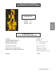
Specification Sheet DIMENSIONS DEPTH: 58 in. WIDTH: 50 in. HEIGHT: 100 in. PERFORMANCE AND POWER REQUIREMENTS TORQUE: MAXIMUM PIPE ROTATION: WRENCH SIZE RANGE: SPINNER SIZE RANGE: 100,000 ft. lbs. 50 degrees 4" __ 9 1/2" OD tool joints 3" __ 9 1/2" OD tube AIR POWER SOURCE: HYDRAULIC POWER SOURCE: HYDRAULIC POWER SOURCE TYPE: 100 psi @ 2-10 cfm 2,600 psi @ 20-35 gpm Closed Center System (Optional Open/Closed Center) WEIGHT: 3,700 lbs.
Ordering Instructions All parts must be ordered by giving the quantity needed, the full part number as listed in this manual under Part #, the unit serial number, the model number and part name.
Hanging Cable Location 1. Anchor the hanging cable to a point as close to the derrick crown as possible. The longer the hanging cable, the easier the HawkJaw is to move on and off the drill pipe. 2. Locate the cable hang point as high above the center of the rotary table as possible. The cable must hang within 2'-3' ft. of the rotary table center. NOTE The hanging cable must permit the HawkJaw to move from the drill pipe connection to the mouse hole connection to the HawkJaw rest position (3'- 5' ft.
Hanging Cable Requirements 1. 5/8" diameter steel cable. 2. Appropriate hanging cable hardware for 5/8" diameter steel cable. 3. Enough cable length to suspend the Hanger Eye (HE) 20' ft. above the rig floor. 4. Enough cable length to allow the HawkJaw to rest on the rig floor 3'- 5' ft. away from the rotary table with the lift cylinder com pletely stroked out. The lift cylinder is 13' ft. long when completely stroked out.
Hydraulic Requirements 1. Pressure compensated pump set to pressure compensate at 2500 psi. 2. Minimum volume of 20 gpm. 35 gpm for top performance. 3. 1" minimum Pressure line. 1 1/4" Pressure line if the power unit is located more than 100' apart from the HawkJaw. The hose working pressure must be 3000 psi or greater. 4. 1 1/4" minimum Tank line. 500 psi minimum hose working pressure. 5. Hawk approved quick disconnects [Male: Part # 061-H52 (MQD). Female: Part # 061-H53 (FQD)].
Air Requirements 1. Clean, dry air at 100 psi @ a negligible volume. 2. On-board auto-dump air filter (Part # 061-A22). Initial on-board filter (OF) supplied with the HawkJaw. 3. Auto-dump air filter (Part # 061-J29) located between the air source and the HawkJaw air supply line (A). Initial inline filter supplied with the HawkJaw. 4. Enough slack in the line for the HawkJaw to move from its rest position to the drill pipe connection to the mouse hole connection.
Raise/Lower Cylinder Hook-Up 1. Use the Raise/Lower cylinder Cap side Bolt (B) to connect the HawkJaw Suspension Ring (SR) to the Raise/ Lower cylinder (C). 2. Use the Raise/Lower cylinder Cap side Lock Nut (N) to secure the Raise/Lower cylinder Cap side Bolt (B). 3. Connect the Hanger Swivel (HS) to the hanging cable. 4. Connect the HawkJaw Rod side (HR) and Cap side (HC) hydraulic Leader hoses to the Raise/Lower cylinder Rod side (RR) and Cap side (RC) hoses.
Winch Hook-Up 1. Connect the air power source with the Air (A) line. 2. Make sure the hydraulic reservoir is full. 3. Connect the hydraulic Pressure (P) and Tank (T) lines. The Pressure line (P) Quick Disconnect is male. 4. Make sure the “E” stop (E) is pulled out. 5. Check for hydraulic leaks. If leaks occur, see Trouble Shooting. 6. With the exception of the hooks retracting, no motion should occur. If any other parts on the HawkJaw move, see Trouble Shooting. Continued on next page...
Winch Hook-Up New 7. Center the Suspension Ring (SR) on the Lateral tilt screw (LTS). 8. Use Raise (R) to raise the HawkJaw 1'- 2' ft. off the rig floor. 9. Use the Control Handle (CH) on both Control Panels and Raise (R) and Lower (L) to position the HawkJaw middle wrench (MW) near the drill pipe shoulder (S) location. SR LTS Continued on next page...
Winch Hook-Up 10. Disengage the Winch Clutch (C). Spool out enough line to anchor the Winch Cable Spring Shackle (S) to a structural point on the derrick. 11. Anchor the Winch Cable Spring Shackle (S) to a structural point on the derrick. Make sure there is enough slack in the line to enable the HawkJaw to move onto the drill pipe connection. 12. Engage the Winch Clutch (C). 13. Use Winch Off (WOff) to pull the HawkJaw 3' to 5' ft. away from the wellbore.
Start-Up Procedure 1. Connect the air power source with the Air (A) line. 2. Make sure the hydraulic reservoir is full. 3. Connect the hydraulic Pressure (P) and Tank (T) lines. The Pressure line (P) Quick Disconnect is male. 4. Make sure the “E” stop (E) is pulled out. 5. Check for hydraulic leaks. If leaks occur, see Trouble Shooting. 6. With the exception of the hooks retracting, no motion should occur. If any other parts on the HawkJaw move, see Trouble Shooting.
Adjust for Make Up MN Adjusting the Wrenches 1. Measure the tool joint with OD calipers. 2. Use the 1 1/4" wrench to adjust the Pointer (P) on the Pipe stop index (PI) to the OD tool joint size. It’s always better to adjust the pointer 1/4" larger than the measured diameter of the tool joint. 3. For safety, adjust the Bottom wrench nut (BN) 1" larger than the Top wrench nut (TN) and Middle wrench nut (MN). 4. Rotate the Top wrench nut (TN) and the Middle wrench nut (MN) to the OD tool joint size.
Adjust for Make Up QR Adjusting the Spinner 1. Measure the drill pipe tube with OD calipers. 2. Remove the quick release pins (QR). 3. Slide the whole Drive unit (D) forward or backward to the appropriate holes. Use the pipe size index (I) to adjust the drive unit to the correct setting. 4. Replace the quick release pins (QR).
Position for Make Up SR 1. Stab the drill stand. 2. Center the Suspension Ring (SR) on the Lateral tilt screw (LTS). 3. Push and hold down Winch On (WOn) to move the HawkJaw onto the drill pipe connection. 4. Use Raise (R) and Lower (L) to center the Top wrench dies (TD) and the Middle wrench dies (MD) between the shoulder (S). 5. Keep the Middle wrench dies (MD) away from the Hard banding (HB). 6. Keep the Top wrench dies (TD) and Middle wrench dies (MD) away from the shoulder (S).
Position for Make Up (cont.) TW 7. Check that the HawkJaw Top wrench (TW), Middle wrench (MW) and Bottom wrench (BW) hang straight and level when the drill pipe is against the pipe stop. 8. If the HawkJaw wrenches (TW, MW, BW) hang tilted forward or backward, use the Top Tilt (TT) button or the Bottom Tilt (BT) button to level the wrenches. Center the level bubble (LB). 9.
Setting Make Up Torque SS 1. Follow the steps on pages 17-21. 2. Turn the Selector Switch (SS) to Make. 3. Use the Red needle adjust (RNA) to rotate the Torque gauge red needle (RN) to the desired torque. 4. Rotate the Torque Set knob (K) counter- clockwise as far as the Torque Set knob (K) will turn. 5. Press in the Grip Hold (GH) button. 6. Press and hold Spin (S) until the stand rotates down to the shoulder. 7. Release Spin (S). Immediately press and hold Grip (G). 8.
Make Up G 1. Press in the Grip Hold (GH) button. 2. Press and hold Spin (S) until the stand rotates down to the shoulder. 3. Release Spin (S). 4. Push in and hold the wrench Grip (G). 5. Push and hold down Torque (T). 6. Watch the Torque gauge needle (TN). 7. When the Torque gauge needle rises above and settles at the desired torque (this rising above is a normal hydraulic adjustment), release Torque (T). Immediately release Torque (T) button and the wrench Grip (G) button. 7a.
Low Torque Warning Test T G E CHECK If the Torque cylinder strokes out before the desired torque is reached, the Torque gauge needle (TN) will fall off to approximately a 8000 Ft.-Lb. reading. If this happens, release Torque (T). Immediately release Grip (G). Wait for the Torque cylinder to reset. LOW TORQUE WARNING SYSTEM CHECK Test#1: Hawk strongly recommends testing the Low Torque Warning System on every trip. If this test procedure is not performed, the drill string could be over torqued.
Adjust for Break Out MN Adjusting the Wrenches 1. Measure the tool joint with OD calipers. 2. Use the 1 1/4" wrench to adjust the Pointer (P) on the Pipe stop index (PI) to the OD tool joint size. It’s always better to adjust the pointer 1/4" larger than the measured diameter of the tool joint. 3. For safety, adjust the Top wrench nut (TN) 1" larger than the Middle wrench nut (MN) and the Bottom wrench nut (BN). 4. Rotate the Middle wrench nut (MN) and the Bottom wrench nut (BN) to the OD tool joint size.
Adjust for Break Out QR Adjusting the Spinner 1. Measure the drill pipe tube with OD calipers. 2. Remove the quick release pins (QR). 3. Slide the whole Drive unit (D) forward or backward to the appropriate holes. Use the pipe size index (I) to adjust the drive unit to the correct setting. 4. Replace the quick release pins (QR).
Position for Break Out SR 1. Center the Suspension Ring (SR) on the Lateral tilt screw (LTS). 2. Push and hold down Winch On (WOn) to move the HawkJaw onto the drill pipe connection. 3. Use Raise (R) and Lower (L) to center the Middle wrench dies (MD) and the Bottom wrench dies (BD) between the shoulder (S). 4. Keep the Bottom wrench dies (BD) away from the Hard banding (HB). 5. Keep the Middle wrench dies (MD) and Bottom wrench dies (BD) away from the shoulder (S). LTS Continued on next page...
Position for Break Out TW 6. Check that the HawkJaw Top wrench (TW), Middle wrench (MW) and Bottom wrench (BW) hang straight and level when the drill pipe is against the pipe stop. 7. If the HawkJaw wrenches (TW, MW, BW) hang tilted forward or backward, use the Top Tilt (TT) button or the Bottom Tilt (BT) button to level the wrenches. Center the level bubble (LB). 8.
Break Out SS 1. Rotate the Selector Switch (SS) clockwise to the break position. 2. Push in the Grip Hold (GH) button. 3. Push and hold in the wrench Grip (G). 4. Push and hold down Torque (T). 5. When break out occurs, release Torque (T). Immediately release the wrench Grip (G). See note below. 6. Press and hold down Spin (S) until the stand pops out of the connection. Release Spin (S). If the stand will not spin, release Spin (S). Repeat Steps 4-6. 7. Pull out the Grip Hold (GH) button. 8.
Wrench Maintenance TW Grease Once per Trip Tools Required Grease gun Initial Steps 1. Make sure the HawkJaw is off the drill pipe connection and in the rest position on the derrick. 2. Shut down the Hydraulic power unit. 3. Press the Grip button repeatedly to bleed hydraulic pressure. 4. Disconnect the Air power supply. 5. Push in the “E” stop. 6. Assume that there is still a load on every actuator. Proceed with caution. Die Pivot Blocks 1.
Wrench Maintenance NS Grease Once per Week, Minimum T N Wrench Hook 1. Surface grease the hook thread (T) on the top wrench, middle wrench, and bottom wrench. 2. Rotate the wrench nut (N) on the top wrench, middle wrench, and bottom wrench to spread grease on the full thread area. Wrench Nut H1 1. Surface grease the wrench nut surface (NS) on the top wrench, middle wrench, and bottom wrench. Hook Pivot Bearing Cap 1.
Wrench Maintenance G1 Grease Once per Week, Minimum Tools Required Grease gun Initial Steps 1. Make sure the HawkJaw is off the drill pipe connection and in the rest position on the derrick. 2. Shut down the Hydraulic power unit. 3. Press the Grip button repeatedly to bleed hydraulic pressure. 4. Disconnect the Air power supply. 5. Push in the “E” stop. 6. Assume that there is still a load on every actuator. Proceed with caution. G2 Grip Cylinder Pivot Points 1.
Wrench Maintenance Grease Once per Week, Minimum MP1 M1 MP2 MP3 Tools Required Grease gun Initial Steps 1. Make sure the HawkJaw is off the drill pipe connection and in the rest position on the derrick. 2. Shut down the Hydraulic power unit. 3. Press the Grip button repeatedly to bleed hydraulic pressure. 4. Disconnect the Air power supply. 5. Push in the “E” stop. 6. Assume that there is still a load on every actuator. Proceed with caution. M2 E Mounting Arm Pivot Points 1.
Filter Maintenance Change Every 2 Months RB Initial Steps WARNING 1. Depress the Red button (RB) located under the See-through rubber weather cap (SC). 2. Operate the HawkJaw. 3. If the Red button pops up, proceed with Step 4. 4. Make sure the HawkJaw is off the drill pipe connection and in the rest position on the derrick. 5. Shut down the Hydraulic power unit. 6. Press the Grip button repeatedly to bleed hydraulic pressure. 7. Disconnect the Air power supply. 8. Push in the “E” stop. 9.
Filter Maintenance CB Change Every 2 Months INITIAL STEPS FC 1. Disconnect the Air power supply. 2. Bleed Air Pressure. S SC Air Filters G 1. Remove the two right Corner bolts (CB). 2. Slide out the Second stage filter cartridge (SC) and Star spacers (S). 3. Slide out the First stage filter cartridge (FC) and Star spacers (S). 4. Slide in the new First stage filter cartridge and Star spacers (S). 5. Slide in the new Second stage filter cartridge and Star spacers (S). 6.
Changing the Hook Dies B Tools Required 3/4" wrench, See Drawings. INITIAL STEPS 1. Make sure the HawkJaw is off the drill pipe connection and in the rest position on the derrick. 2. Shut down the Hydraulic power unit. 3. Press the Grip button repeatedly to bleed hydraulic pressure. 4. Disconnect the Air power supply. 5. Push in the “E” stop. 6. Assume that there is still a load on every actuator. Proceed with caution. DR DH D Hook Dies 1. Use the 3/4" wrench to remove the Die Holder Bolts (B).
Changing the Heel Dies RB B P Tools Required 3/4" wrench, See Drawings. INITIAL STEPS 1. Make sure the HawkJaw is off the drill pipe connection and in the rest position on the derrick. 2. Shut down the Hydraulic power unit. 3. Press the Grip button repeatedly to bleed hydraulic pressure. 4. Disconnect the Air power supply. 5. Push in the “E” stop. 6. Assume that there is still a load on every actuator. Proceed with caution. R DR D Top Wrench Heel Die 1.
Changing the Heel Dies 7. Make sure the back and sides of the new Die are clean. 8. Grease the back of the new Die. 9. Insert the new Die into the Die Holder (DH) with the teeth of the Die facing out. 10. Replace the Top Die Retainer (DR). 11. Insert the Heel Die Pin (P). 12. Replace the Heel Die Rollers (R). 13. Replace the Roller Bushings (RB). 14. Use the 3/4" wrench to replace the Heel Die Roller Bolts (B) and Lock Washers.
Changing the Heel Dies Initial Steps 1. Make sure the HawkJaw is off the drill pipe connection and in the rest position on the derrick. 2. Shut down the Hydraulic power unit. 3. Press the Grip button repeatedly to bleed hydraulic pressure. 4. Disconnect the Air power supply. 5. Push in the “E” stop. 6. Assume that there is still a load on every actuator. Proceed with caution. P B DR Middle Wrench Heel Die 1. Use the 3/4" wrench to remove the Heel Die Roller Bolts (B). 2. Pull out the Heel Die Pin (P).
Changing the Heel Dies 8. Replace the Top Die Retainer (DR). 9. Insert the Heel Die Pin (P). 10. Use the 3/4" wrench to replace the Heel Die Roller Bolt (B) and Lock Washers.
Changing the Heel Dies Tools Required B DR P 3/4" wrench, See Drawings. Initial Steps 1. Make sure the HawkJaw is off the drill pipe connection and in the rest position on the derrick. 2. Shut down the Hydraulic power unit. 3. Press the Grip button repeatedly to bleed hydraulic pressure. 4. Disconnect the Air power supply. 5. Push in the “E” stop. 6. Assume that there is still a load on every actuator. Proceed with caution. D Bottom Wrench Heel Die 1.
Changing the Heel Dies B 6. Grease the back of the new Die. 7. Insert the new Die into the Die Holder (DH) with the teeth of the Die facing out. 8. Replace the Top Die Retainer (DR). 9. Insert the Heel Die Pin (P). 10. Use the 3/4" wrench to replace the Heel Die Bolts (B) and Lock Washers.
Spinner Maintenance GH Notice Spinner chain lubrication must be done during normal operation of the Hawkjaw. Do not run the spinner when the Hawkjaw is not on the pipe. Initial Steps 1. Position the Hawkjaw for breakout. Chain Lubrication 1. Pull the Hawkjaw onto the pipe. 2. Press in the Grip Hold (GH) button. 3. Press and hold the Spin (S) button. While holding down the Spin (S) but ton, press and hold the Chain Oiler (CO) button for 3 seconds. 4. Release the Spin (S) button. 5.
Spinner Maintenance Grease Once Per Month GI BC G3 Tools Required Grease gun, 7/16” wrench Initial Steps 1. Make sure the HawkJaw is off the drill pipe connection and in the rest position on the derrick. 2. Shut down the Hydraulic power unit. 3. Press the Grip button repeatedly to bleed hydraulic pressure. 4. Disconnect the Air power supply. 5. Push in the “E” stop. 6. Assume that there is still a load on every actuator. Proceed with caution. G2 G4 Drive Roller Sprocket Bearings 1.
Spinner Maintenance SC1 Grease Once per Month SC2 Tools Required Grease gun Spinner Grip Cylinders 1. Pump grease fittings SC1-SC4. Chain Drive Shaft Bearing 1. Pump grease fitting CB1.
Spinner Maintenance Grease Once per Month ST1 ST2 Tools Required Grease gun Spinner Mount Sliding Tube 1. Pump grease fittings ST1-ST4. Spinner Mount Sliding Block 1. Pump grease fitting SB1. ST3 NOTE Consisten lubrication of the Spinner sliding tube and block increases performance and component life.
Spinner Maintenance RP Grease Once per Month Lubricant Required 85-90 weight gear oil SAE #AGMA5 Reducer Gear Box 1. Make sure the gear box oil level reaches the top pipe plug (RP). Winch Gear Box 1. Make sure the gear box oil level reaches the top pipe plug (WP). NOTE Consistent lubrication of the Spinner and Winch increases performance and component life.
Changing the Spinner Chain S Tools Required SD 7/8" wrench, 7/16" wrench, Hammer, Needle-Nose Pliers Initial Steps 1. Make sure the HawkJaw is off the drill pipe connection and in the rest position on the derrick. 2. Shut down the Hydraulic power unit. 3. Press the Grip button repeatedly to bleed hydraulic pressure. 4. Disconnect the Air power supply. 5. Push in the “E” stop (E). 6. Assume that there is still a load on every actuator. Proceed with caution. B S Chain 1.
Changing the Spinner Chain 6. From the front of the unit, use the Needle-nose pliers to remove the Cotter pins (CP) in one of the Chain links. 7. Use the hammer to remove the Chain link pin (CLP). 8. Pull out the old chain. Make sure the chain does not catch on the Drive Sprocket (DS). 9. Feed the chain into the spinner behind the Drive Sprocket (DS) until both ends of the new chain meet at the Drive roller sprockets (DRS). 10.
Changing the Driver Rollers E Tools Required 3/4" wrench Initial Steps 1. Make sure the HawkJaw is off the drill pipe connection and in the rest position on the derrick. 2. Shut down the Hydraulic power unit. 3. Press the Grip button repeatedly to bleed hydraulic pressure. 4. Disconnect the Air power supply. 5. Press the Grip button repeatedly to bleed hydraulic pressure. 6. Push in the “E” stop (E). 7. Assume that there is still a load on every actuator. Proceed with caution. Drive Rollers 1.
Changing the Driver Rollers 2. Use the 3/4" wrench to remove all Bearing Cap Bolts (9). 3. Remove the Bearing Caps (2) and Bearing Seals (3). 4. Slide out the Drive Roller Sprockets (4). 5. Remove the Drive Roller Snap Rings (7). 6. Remove the Drive Rollers (5) and Keys (6). 7. Slide on the new Drive Rollers and replace the Keys (6). 8. Replace the Drive Roller Snap Rings (7). 9. Slide in the Drive Roller Sprockets (4) . Make sure the “T” on each Drive Roller Sprocket faces up. 10.
Changing the Driver Rollers Sprocket Bearings Tools Required Four 1/4"-20 x 1 1/2" Hex Tap SS (Part # 999-805867), 7/16" wrench, 3/4" wrench Initial Steps 1. Make sure the HawkJaw is off the drill pipe connection and in the rest position on the derrick. 2. Shut down the Hydraulic power unit. 3. Press the Grip button repeatedly to bleed hydraulic pressure. 4. Disconnect the Air power supply. 5. Push in the “E” stop (E). 6. Assume that there is still a load on every actuator. Proceed with caution.
Changing the Driver Roller Sprocket Bearings 4. Use the 7/16" wrench to screw in the Hex Tap screws into the four small threaded holes in the top of the Bearing Caps (2). As the screws tighten, the bearing (8) is pushed out. Tighten the Hex Tap screws evenly, or the bearing (8) will tilt and lodge in the bearing cap (2). 5. Insert the new bearings into the Bearing Caps (2). 6. Replace the Bearing Caps (2) and Bearing Seals (3). 7. Use the 3/4" wrench to replace all Bearing Cap Bolts (9).
Changing the Torque Cylinder GH Initial Steps 1. Make sure the HawkJaw is off the drill pipe connection and in the rest position on the derrick. Torque Cylinder 1. Press Grip Hold (GH). 2. Press and hold Grip (G) 3. While holding down Grip (G), press and hold down Torque (T) until the Torque Cylinder Rod Pin (P) extends out from underneath the Reset Cam (RC). 4. Release both Torque (T) and Grip (G), and immediately push in the “E” stop (E).
Changing the Torque Cylinder 6. Use the 1 1/8" wrench to slowly loosen the Cap side Hoses (CH1), (CH2). Check for fluid flow. Bleed any pressure. Disconnect the Cap side Hoses (CH1), (CH2). 7. Use the 1" wrench to slowly loosen the Rod side Hose (RH). Check for fluid flow. Bleed any pressure. Disconnect the Rod side Hose (RH). 8. Pull out the Torque Cylinder Safety Clip (SC). 9. Use the Torque Cylinder Safety Clip (SC) to pull out the Torque Cylinder Rod Pin (P). 10.
Changing the Torque Cylinder 15. Use air pressure or manual force to extend the new Torque Cylinder Rod to the length of the old Torque Cylinder Rod. 16. Place the Bottom Trunion Mount Plate (BMP) and Top Trunion Mount Plate (TMP) on the new Torque Cylinder. 17. Slide in the new Torque Cylinder. 18. Use the 1 1/8" wrench to replace the Bottom Torque Cylinder Mount Bolts (BB). Use new Lock Washers and red loctite when replacing the Bottom Torque Cylinder Mount Bolts (BB). Assemble the Lock Washers as shown.
Changing the Torque Cylinder 21. Use the 1" and 1 1/8" wrench to connect the Rod side Hose (RH) and the Cap side Hoses (CH1), (CH2). 22. Insert the Torque Cylinder Rod Pin (P). 23. Insert the Torque Cylinder Safety Clip (SC). 24. Make sure no bodily parts are in the retract path of the Torque Cylinder. Turn on the hydraulic power unit. Pull out the “E” stop. The Middle wrench will retract.
Changing the Grip Cylinder E Tools Required Two 11/16" wrenches, Two 1 1/2" wrenches Initial Steps 1. Make sure the HawkJaw is off the drill pipe connection and in the rest position on the derrick. 2. Shut down the Hydraulic power unit. 3. Press the Grip button repeatedly to bleed hydraulic pressure. 4. Disconnect the Air power supply. 5. Push in the “E” stop (E). 6. Assume that there is still a load on every actuator. Proceed with caution. Top Grip Cylinder 1.
Changing the Torque Cylinder CH 3. Use the Two 1 1/2" wrenches to remove the Grip Cylinder Cap side Bolt (CB) and Flex Lock Nut. 4. Use the 1 1/2" wrench to remove the Grip Cylinder Rod side Pin (RP). 5. Slide out the Grip Cylinder (C). 6. Place the new Grip Cylinder into the Cap side Eye (CE) and Rod side Eye (RE). 7. Use the Two 1 1/2" wrenches to replace the Grip Cylinder Cap side Bolt (CB) and Flex Lock Nut. 8. Replace the Grip Cylinder Rod side Bolt (RB). Assemble with cotter pin. 9.
Changing the Grip Cylinder E Tools Required Two 11/16" wrenches, Two 1 1/2" wrenches Initial Steps 1. Make sure the HawkJaw is off the drill pipe connection and in the rest position on the derrick. 2. Follow Steps 1-4 on p. 52. Middle Grip Cylinder 1. Use the Two 11/16" wrenches to slowly loosen the Rod side Hose (RH). Check for fluid flow. Bleed any pressure. Disconnect the Rod side Hose (RH). 2. Use the Two 11/16" wrenches to slowly loosen the Cap side Hose (CH). Check for fluid flow.
Changing the Torque Cylinder CB 6. Place the new Grip Cylinder into the Cap side Eye (CE) and Rod side Eye (RE). 7. Use the Two 1 1/2" wrenches to replace the Grip Cylinder Cap side Bolt (CB). 8. Replace the Grip Cylinder Rod side Bolt (RB). Assemble with cotter pin. 9. Use the Two 11/16" wrenches to connect the Cap side Hose (CH). 10. Use the Two 11/16" wrenches to connect the Rod side Hose (RH). 11. Make sure no bodily parts are in the retract path of the Torque Cylinder.
Changing the Grip Cylinder E Initial Steps 1. Make sure the HawkJaw is off the drill pipe connection and in the rest position on the derrick. 2. Shut down the Hydraulic power unit. 3. Press the Grip button repeatedly to bleed hydraulic pressure. 4. Disconnect the Air power supply. 5. Push in the “E” stop (E). 6. Assume that there is still a load on every actuator. Proceed with caution. Bottom Grip Cylinder 1. Use the Two 11/16" wrenches to slowly loosen the Rod side Hose (RH). Check for fluid flow.
Changing the Grip Cylinder CB 3. Use the Two 1 1/2" wrenches to remove the Grip Cylinder Cap side Bolt (CB) and Flex Lock Nut. 4. Use the 1 1/2" wrench to remove the Grip Cylinder Rod side Bolt (RB). 5. Slide out the Grip Cylinder (C). 6. Place the new Grip Cylinder into the Cap side Eye (CE) and Rod side Eye (RE). 7. Use the Two 1 1/2" wrenches to replace the Grip Cylinder Cap side Bolt (CB) and Flex Lock Nut. 8. Replace the Grip Cylinder Rod side Bolt (RB). 9.
Main Hydraulic Block Fitting and Hose Access Initial Steps 1. Make sure the HawkJaw is off the drill pipe connection and in the rest position on the derrick. 2. Use Raise (R) to raise the HawkJaw 6"-12" inches off the derrick floor. 3. Shut down the Hydraulic power unit. 4. Press the Grip button repeatedly to bleed hydraulic pressure. 5. Disconnect the Air power supply. 6. Push in the “E” stop (E). 7. Assume that there is still a load on every actuator. Proceed with caution.
Main Hydraulic Block Fitting and Hose Access Initial Steps 1. Make sure the HawkJaw is off the drill pipe connection and in the rest position on the derrick. 2. Use Raise (R) to raise the HawkJaw 3"-5" inches off the derrick floor. 3. Shut down the Hydraulic power unit. 4. Press the Grip button repeatedly to bleed hydraulic pressure. 5. Disconnect the Air power supply. 6. Push in the “E” stop (E). 7. Assume that there is still a load on every actuator. Proceed with caution.
Main Hydraulic Block Fitting and Hose Access E Tools Required 3/4" wrench, 3/16" Allen wrench Initial Steps 1. Make sure the HawkJaw is off the drill pipe connection and in the rest position on the derrick. 2. Shut down the Hydraulic power unit. 3. Press the Grip button repeatedly to bleed hydraulic pressure. 4. Disconnect the Air power supply. 5. Push in the “E” stop (E). 6. Assume that there is still a load on every actuator. Proceed with caution. C Spinner Motor Sequence Valve 1.
Trouble Shooting Problem Remedy Hose leaks. • Replace the hose. See Drawings. All Grip cylinders extend, and the Torque cylinder extends. • The Pressure and Tank lines are switched. Properly One or more Grip cylinders extend. • Make sure the hydraulic power unit is shut down. connect the Pressure and Tank lines. See Operation. Press the Grip button repeatedly to bleed hydraulic pressure. Properly connect the Rod side and Cap side hoses to the Grip cylinder. See Maintenance & Repair & Drawings.
Trouble Shooting Problem Remedy Spinner pops off the drill pipe tube when the spinner rotates the pipe. spinner is adjusted too small for the drill pipe • The tube. Adjust the spinner to the correct pipe size. Spinner Drive Rollers touch when the spinner clamps onto the drill pipe tube. • Spinner does not slide forward on the spin mount block or does slide forward and closes prematurely and bangs on pipe body while closing. • Spinner chain hinders the correct alignment of the HawkJaw on the pipe.
Trouble Shooting Problem Remedy Spinner begins to spin before the spinner doors close on the drill pipe tube. (Cont.) • Spinner moves forward and the doors close on the pipe, but the spinner does not spin. • Spinner retracts from the pipe and forces the HawkJaw back away from the pipe. • Spinner chain slips on the drill pipe tube. • Spinner chain wears out prematurely. • • • Drill pipe does not rotate down to the shoulder, or Spinner performance and speed not up to par.
Trouble Shooting Problem Spinner Drill pipe does not rotate down Performance to the shoulder, or Spinner performance and speed not up to par. (cont.) The filter element is clogged. Replace the filter element. See Maintenance & Repair. The air pressure is low. Increase the air pressure to the HawkJaw. See Installation. Check to make sure the hydraulic power unit is producing 2500 psi at 20-35 gpm. Check to make sure the hydraulic power unit pressure compensator setting is at 2500 psi.
Trouble Shooting Problem HawkJaw performance and speed not up to par. . . . . . . . Remedy See that they are securely tightened. A bad quick disconnect can cause the Hawkjaw to mal-function. Replace the faulty connector. The air pressure is low. Increase the air pressure to the HawkJaw. See Installation. Check to make sure the hydraulic power unit is producing 2500 psi at 20-35 gpm. Check to make sure the hydraulic power unit pressure compensator setting is at 2500 psi.
Trouble Shooting Problem HawkJaw performance and speed not up to par. . . While in make-up mode, a desired torque setting cannot be achieved or the torque control valve will not effect the torque output of the Hawkjaw. 72 Trouble Shooting . Remedy There is a leak in the hydraulic system. Make sure the air supply hose to the HawkJaw is disconnected. Make sure the hydraulic power unit is on. Check for Torque cylinder piston seal integrity.
Trouble Shooting Problem Hydraulic fluid heats up. The Raise/Lower Cylinder moves slower than usual, or the HawkJaw sinks while it hangs.. . . . . . . Remedy There is a leak in the hydraulic system. See Trouble Shooting. Check to make sure the hydraulic power unit is producing 2500 psi at 20-35 gpm. Check that the HawkJaw is getting at least 100 psi air. Check that the pump pressure compensator setting is at 2500 psi. Check that the hydraulic filter element is not completely full of contaminants.
Trouble Shooting Problem The Raise/Lower Cylinder moves at an undesired speed. The Tilt Cylinder moves at an undesired speed. The mount arms do not pivot freely. Push in the Winch On orWinch Off button, and the HawkJaw moves opposite the desired direction. Winch does not operate. 74 Trouble Shooting . . . . . . . . . . . . . Remedy Push in the “E” stop button. Access the main hydraulic block. See Maintenance & Repair & Drawings.
Trouble Shooting Problem . . . The Tilt Cylinder moves at an undesired speed. The Low torque warning system Test #1 has failed. The Low torque warning system Test #2 has failed. . . . Remedy -pletely full of contaminants. If the red indicator button on the hydraulic filter body pops up, change the filter element. See Filter Maintenance. Check that no hissing sound comes from the Winch On or Winch Off button. An air hose is broken, switched or disconnected if there is a hissing sound.
Trouble Shooting Problem The Low torque warning system Test #1 has failed. The Low torque warning system Test #2 has failed. 76 Trouble Shooting . . Remedy The low torque warning poppet pin #061-30064 and #061-20238 poppet seat may have seal damage or the bellville springs #061-022S need replacement or correct placement. See Drawings. To check poppet seal damage, refer to page 23 for LOW TORQUE WARNING TEST #1 PROCEDURES. The low torque warning small “U” cup seal is leaking. Replace the seal.
Notes Trouble Shooting 77
100K-2GSR Full Hawkjaw Assembly 78 Drawings
100K-2GSR Full Hawkjaw Assembly ITEM NO. QUANTITY 1 2 3 4 5 6 7 8 9 10 11 12 1 1 1 1 1 1 1 1 1 1 1 1 PART NO.
100K-2GSR Top-Bottom Wrench Assembly 80 Drawings
100K-2GSR Top-Bottom Wrench Assembly ITEM 1 2 3 4 5 6 7 8 9 10 11 12 13 14 15 16 17 18 19 20 21 22 23 24 25 26 27 28 29 30 31 32 33 34 35 36 37 38 39 40 41 42 43 44 45 46 47 48 49 50 51 52 53 54 55 56 57 58 59 60 61 62 63 64 65 66 67 68 69 70 QTY. 1 1 1 1 1 1 10 2 2 2 1 2 2 2 4 2 8 2 2 4 4 1 4 4 7 2 2 8 10 8 2 4 2 1 4 2 2 1 1 1 2 4 4 2 2 4 4 22 4 1 2 1 2 2 2 1 1 1 1 1 1 1 1 4 2 2 8 4 16 1 PART NO.
. *65 0LGGOH :UHQFK $VVHPEO\ 82 Drawings
. *65 0LGGOH :UHQFK $VVHPEO\ ,7(0 12 3$57 180%(5 '(6&5,37,21 47< $ $ $ % . . + 6 $ /0 0,' $ .
100K-2GSR Hydro-Pneumatic Assembly 84 Drawings
100K-2GSR Hydro-Pneumatic Assembly ITEM 1 2 3 4 5 6 7 8 9 10 11 12 13 14 15 16 17 18 19 QTY. 1 1 1 1 1 1 8 14 8 6 4 8 4 1 1 1 1 2 1 PART NO./DESCRIPTION 100K-2GSR Hydraulic Connections (J1A-A) 20169 Control Housing Assembly 20176A Block Plate Assembly 20167-2 Inspection Cover 20167-3A Inspection Cover 20162A Control Housing Assembly 806244_1.2-13 x 1.0 Hex Bolt 810703_1.2 Lock W asher 810705_1.2 Flat W asher 806239_1.2-13 x .75lg. Hex Bolt 806003_3.8-16 x .75 lg. Hex Bolt 810645_3.
100K-2GSR Hanger Assembly 86 Drawings
100K-2GSR Hanger Assembly ITEM 1 2 3 4 5 6 7 8 9 10 11 12 13 14 15 16 17 18 19 20 21 22 23 24 25 26 27 28 29 30 31 32 33 34 35 36 37 38 39 40 41 42 43 44 45 46 Q TY. 1 1 1 1 1 2 2 2 1 1 1 1 1 6 6 1 1 1 3 1 1 2 1 1 1 2 2 2 4 2 2 1 3 3 1 2 2 2 1 2 1 1 1 1 1 1 PART NO ./DESCRIPTIO N 20147 Hanger Assembly 20151 Spindle Bloc k 20267 Hose Mount, 2GSR Assembly 20059 U Bolt for 2GSR H18S Grip Tilt Cy linder Assembly SH30540PP 1.4 Hose Clamp (pipe) SH5150PP 1_1.
100K-2GSR Left Control Handle Assembly 88 Drawings
100K-2GSR Left Control Handle Assembly ITEM NO. QUANTITY 1 2 3 4 5 6 7 8 9 10 11 12 13 14 15 16 17 18 1 1 1 2 4 4 1 1 4 4 2 1 1 1 1 5 1 1 PART NO./ DESCRIPTION 70100 Left Control Handle Assembly 70103 Left Control Panel A ssembly A15 Air Manifold 20104-1 Control Handle, Top & Bottom Cover 805916_5.16-18 x .50 LG. HEX BOLT 810616_5.16 Loc k W asher 2 806004_3.8-16 x .75 Lg. Hex Bolt 2 810645_3.8 Loc k W asher 806041_3.8-16 x 2.00 lg. Hex Bolt Grd. 5 805987-750 3.
100K-2GSR Right Control Handle Assembly 90 Drawings
100K-2GSR Right Control Handle Assembly ITEM NO. QUANTITY 1 2 3 4 5 6 7 8 9 10 11 12 13 14 15 16 17 18 19 20 21 22 23 24 25 26 27 28 29 30 1 1 4 4 12 12 4 6 1 2 1 1 1 1 2 1 1 1 2 1 1 1 2 2 1 1 1 1 1 2 PART NO./ DESCRIPTION 70101 Right Control Handle Assembly 70105 Right Control Panel Assembly 805916_5.16-18 x .50 LG. HEX BOLT 810616_5.16 Lock W asher 806004_3.8-16 x .75 Lg. Hex Bolt 810645_3.8 Lock Washer 806041_3.8-16 x 2.00 lg. Hex Bolt Grd. 5 805987-750 3.
100K-2GSR Winch Mount Assembly 92 Drawings
100K-2GSR Winch Mount Assembly ITEM NO. QUANTITY 1 2 3 4 5 6 7 8 9 10 11 12 13 14 1 1 1 1 4 2 4 2 6 8 2 2 1 1 PART NO./ DESCRIPTION COMMENTS 20223 W inch Mount Assembly H59R W inch Assembly, Manual 59R Roller Assembly , W inch 20286 W inch Cover 20203 Spacer, Winch 806542-1_3.4-16 x 4.50 Hex Bolt 91074A036 Lock W asher Assembly, 3.4 806542_3.4-16 X 4.50lg. Soc. Hd. Cap Screw 806284_1.2-13 x 2.00lg. Hex Bolt 810703_1.2 Lock W asher 806244_1.2-13 x 1.
100K-2GSR Spinner Mount Assembly 94 Drawings
100K-2GSR Spinner Mount Assembly ITEM NO. QUANTITY 1 2 3 4 5 6 7 8 9 10 11 12 13 14 15 16 17 18 19 20 21 22 23 24 25 26 27 28 29 30 31 32 33 34 35 36 37 38 39 40 41 1 1 1 1 2 2 1 1 1 4 4 2 2 1 1 1 1 7 1 1 4 6 6 2 6 1 1 2 2 2 1 1 1 1 1 1 2 1 1 4 4 PART NO.
100K-2GSR Stand Assembly 96 Drawings
100K-2GSR Stand Assembly ITEM NO. QUANTITY 1 2 3 4 5 6 7 8 9 10 1 1 2 6 7 1 1 1 2 2 PART NO./ DESCRIPTION COMMENTS 20075A Stand Assembly 806542-1_3.4-16 x 4.50 Hex Bolt 91074A036 Lock W asher Assembly, 3.4 806436_5.8-11 x 1.50 lg. Hex Bolt Grd. 9 810732_5.8 Lock Washer 806439_5.8-11 x 2.50 lg Hex Bolt Grd. 9 806538_3.4-16 x 2.00 lg. Hex Bolt Grd. 9 806594-500_1-14 Lock Nut 806414-500_5.8-11 Flex Nut (31FA1011) 806438_5.8-11 x 2.00 lg Hex Bolt Grd.
100K-2GSR Hawkjaw Spinner Assembly 98 Drawings
K-2GSR Hawkjaw Spinner Assembly ITEM NO. QUANTITY 1 2 3 4 5 6 7 8 9 10 11 12 13 14 15 16 17 18 19 20 21 22 23 24 25 26 27 28 29 30 31 32 33 34 35 36 37 38 39 40 41 42 43 44 45 46 47 48 49 50 51 52 53 54 55 56 57 58 59 60 61 62 63 64 65 66 67 68 69 70 71 72 73 74 75 76 1 4 1 1 1 4 1 1 1 1 1 1 3 2 1 1 4 4 2 4 4 4 4 2 2 4 2 4 4 4 1 1 1 1 4 8 2 5 2 2 2 2 20 5 8 8 2 8 1 1 2 8 8 1 20 2 4 2 4 1 4 4 2 1 3 1 2 2 1 2 1 1 2 1 4 4 PART NO.
100K-2GSR Pipe Stop Assembly 100 Drawings
100K-2GSR Pipe Stop Assembly ITEM NO. QUANTITY 1 1 2 3 4 5 6 7 8 9 10 12 13 14 15 16 18 19 20 21 22 23 24 25 26 27 1 1 1 1 4 1 1 1 1 4 1 1 1 2 1 1 1 1 1 4 4 1 1 1 1 1 PART NO./ DESCRIPTION COMMENTS 25710-SR Case Assembly, Stationary 20066 Pointer 20060 Adjust Clevis 20050 Linkage, Stop Assembly 809403_10-32x.375 Screw SS 20041A Pipe Stop Rubber 20029-250 Washer, Pipe Stop 20214-3 Hex Bolt 806414-500_5.
100K-2GSR Hydraulic Connections 102 Drawings
100K-2GSR Hydraulic Connections ITEM QTY PART NO./ DESCRIPTION 1 2 3 4 5 6 7 8 9 10 1 1 1 2 2 2 1 2 2 6 100K-2GSR Main Manifold Assembly (J1A-A) HOS-12_-10FJICx-10FJICx35.00lg. Hose HOS-132G_-10FJICx-10FJICx 110.0lg-10. Hose HOS-82G_-8FJICx-8FJICx100.00lg. Hose HOS-42G_1.4MNPTx-4FJICx117.00lg. Hose HOS-102G_-10FJICx-10FJICx115.00lg. Hose HOS-72G_-8FJICx-8FJICx92.00lg-8. Hose HOS-52G_-4FJICx-4FJICx86.00lg-4. Hose TB, HOS-142G_-6FJICx-6FJICx95.00lg-6. Hose HOS-62G_-6FJICx-6FJICx36.00lg.
100K-2GSR Spin Manifold Assembly 104 Drawings
100K-2GSR Spin Manifold Assembly IT E M Q TY. 1 1 2 1 3 1 4 1 5 2 6 1 7 1 H38 H35 H34 H31 H33 H36 H45 P AR T N O .
100K-2GSR Raise/Lower Cylinder Assembly 106 Drawings
100K-2GSR Raise/Lower Cylinder Assembly ITEM NO. QUANTITY 1 2 3 4 5 6 7 8 9 10 11 12 13 14 15 16 17 18 19 20 1 1 1 1 1 2 1 1 1 1 1 2 1 1 1 1 2 1 1 1 PART NO./ DESCRIPTION 2572-9 Barrel, Raise Lower Cylinder 2572-6 Rod, Raise Lower Cylinder 2572-8 Rod Clevis, Raise Lower Cylinder 2572-7 Seal Retainer, Raise Lower Cylinder TPO-28 Piston Seal TPO-28 Backup, Piston Seal 940-15 Rod W iper, Raise Lower Cylinder MCD-2500-1000 W ear Ring, Raise lower Cylinder 2-228-90 O Ring 2572-5 Cotter Pin 3.16 dia. x 3.
100K-2GSR Main Manifold Assembly 108 Drawings
100K-2GSR Main Manifold Assembly ITEM 1 2 3 4 5 6 7 8 9 10 11 12 13 14 15 16 17 18 19 20 21 22 23 24 25 26 27 28 29 30 31 32 33 34 35 36 37 QTY. 1 6 14 1 2 2 1 1 2 2 1 1 2 1 1 1 1 1 1 1 1 1 1 1 2 3 4 8 2 2 1 3 2 6 2 1 1 PART NO./DESCRIPTION J1A Main Manifold H6 Flow Control Sandwich Assembly A25 5.32 x 1.4 PTC Elbow H35 Sequence Valve 2062-10-10S_10MORB x 10MJIC Fitting 90 206209-10-10S_10MORB x 10MJIC Fitting 90 Ext. 206209-6-6S_6MORB x 6MJIC Fitting 90 Ext.
100K-2GSR Main Manifold Air Connections 110 Drawings
100K-2GSR Main Manifold Air Connections LEFT CONNECTOR DUPLICATE X PORT DESCRIPTION COLOR SIZE A AIR SUPPLY B AIR SUPPLY TORQUE BLACK 3/16 YELLOW C AIR SUPPLY SPIN 5/32 1 AIR SUPPLY WINCH 2 GRIP #1 YELLOW 5/32 3 GRIP #2 ORANGE 5/32 CLEAR 5/32 RED 5/32 4 GRIP #3 BLUE 5/32 5 RAISE VALVE SIDE "b" GREEN 5/32 X 6 LOWER VALVE SIDE "a" BLACK 5/32 X 7 TILT VALVE SIDE "b" CLEAR 5/32 8 TILT VALVE SIDE "a" GREY 5/32 9 OILER BLACK 5/32 RIGHT CONNECTOR DUPLICATE P
100K-2GSR Left Control Handle Air Connections 112 Drawings
100K-2GSR Left Control Handle Air Connections ITEM NO. QTY THIS ASSY. 1 2 3 4 5 6 7 8 9 10 11 12 13 14 15 16 17 19 20 21 22 23 1 16 5 1 1 5 1 1 1 1 4 2 1 5 8 3 1 1 1 10 1 1 PART NO./ DESCRIPTION A15 Air Manifold A40-5 Red Air Hose A36 Port Plug A1 Selector Switch Assembly A8GH Grip Hold Button Assy A3 Button Air Valve Assembly A4G Grip Valve Assembly 2081-4-2S 1.4 x 1.8 H.P. Hex Bushing A47 3.16 x 1.8 PTC Elbow A40L-4_3.
100K-2GSR Right Control Handle Air Connections 114 Drawings
100K-2GSR Right Control Handle Air Connections ITEM NO. QUANTITY 1 2 3 4 5 6 7 8 9 10 11 12 13 14 15 16 17 1 1 1 2 2 5 1 1 1 5 2 2 1 1 1 1 1 PART NO./ DESCRIPTION COMMENTS A 15 Air Manifold A 40 -1 Yellow Air Hose A 40 -2 Orange Air Hose A 40 -8 Gray Air Hose A 40 -4 Clear Air Hose A 36 Port Plug 2081-4 -2S 1.4 x 1.8 H.P. Hex Bushing A 47 3.16 x 1 .8 P TC E lbow A 40 L -4 _ 3.
100K-2GSR Torque Cylinder Assembly 116 Drawings
100K-2GSR Torque Cylinder Assembly ITEM NO. QUANTITY 1 4 5 6 7 10 11 12 15 16 19 23 24 25 26 27 28 30 31 32 33 34 35 36 37 38 39 40 41 42 43 44 1 1 1 1 1 1 1 1 1 1 11 14 2 1 1 2 1 1 1 1 1 1 1 1 1 1 1 1 1 1 1 2 PART NO./ DESCRIPTION 4H080 Tube Assembly 20259 Torque Cylinder Guard 20238 Poppet Seat 30064 Poppet Pin 30065 Body, Poppet Valve LTW-RK U Cup, Poppet Pin PRP568-016 O Ring, Poppet Seat PRP568-018 O Ring, Body 20011_1 1.
100K-2GSR Left Control Tube Assy Air Conn 118 Drawings
100K-2GSR Left Control Tube Assy Air Conn ITEM NO. 1 2 3 QTY THIS ASSY. 1 1 1 PART NO./ DESCRIPTION A11-1LCH Multiplex Connector Assembly A11-LCH Multiplex Connector Assembly A11LFT Left Control Tube Assembly COMMENTS See Explos. Drw. See Explos. Drw.
100K-2GSR Right Control Tube Assy Air Conn 120 Drawings
100K-2GSR Right Control Tube Assy Air Conn ITEM NO. 1 2 3 QTY THIS ASSY. 1 1 1 PART NO.
25726 Chain Oiler Assembly 122 Drawings
25726 Chain Oiler Assembly ITEM NO. QTY THIS ASSY. 3 4 5 6 7 8 9 10 11 12 13 1 1 1 1 1 1 1 2 1 2 1 PART NO./ DESCRIPTION COMMENTS 2083-4-45 1-4 NPT ADAPTER 11432-SSP Body, SST, Polished 8536-200 STRAINER, SST 7894-NY TIP GASKET, NYLON 7894-NY TIP GASKET, NYLON TP400025-TC .013 Nozzle 7890-SSP CAP,SST, POLISHED 805916_5.16-18 x .50 LG. HEX BOLT 2049-2-2 1-8,45 Drg Adapter 810616_5.
20209-BOT Heel Die Holder Assembly, Bottom 124 Drawings
20209-BOT Heel Die Holder Assembly, Bottom ITE M 1 2 3 4 5 6 7 8 9 Q TY. 1 2 1 2 2 2 2 2 2 P AR T N O ./D E S C R IP TIO N 20192-1B D ie Holder, Heel S ide 810703_1.2 Loc k W asher 20194 D ie 20212-1A Retainer, Heel D ie 20208-870 S pac er, D ie Holder 98381A 622_3.8 D ia. x .75 lg. S S D owel P in 20210 Roller A ssembly 806307_1.2-13 x 3.25 lg.
20209-MID Heel Die Holder Assembly, Middle 126 Drawings
20209-MID Heel Die Holder Assembly, Middle IT E M Q T Y. 1 1 2 1 3 1 4 1 5 2 6 1 7 1 8 2 9 1 10 2 11 1 P AR T N O ./D E S C R IP T IO N 2019 2- 1B D ie Holder , Heel S ide 2021 0 Roller A ssem bly 2020 8A S p ac er B ushing, Roller 8062 76_1.2- 13 x 1.7 5 Hex B olt 8107 03_1.2 Loc k W a sher 8107 05_1.2 F lat W ash er 8063 07_1.2- 13 x 3.2 5 lg. Hex B olt 9838 1A 62 2_3.8 D ia. x .75 lg.
20209-TOP Heel Die Holder Assembly, Top 128 Drawings
20209-TOP Heel Die Holder Assembly, Top IT E M N O . Q TY.TH IS AS S Y 1 1 2 2 3 2 4 2 5 2 6 1 7 2 8 2 P AR T N O ./ D E S C R IP T IO N 20192-1B D ie Holder , Heel S ide 20210 Roller A ssembly 20208A S pac er B ushing, Roller 806307_1.2-13 x 3.25 lg. Hex B olt 810703_1.2 Loc k W asher 20194 D ie 20212-1A Retainer, Heel D ie 98381A 622_3.8 D ia. x .75 lg.
20211-MID Hook Die Holder Assembly, Middle 130 Drawings
20211-MID Hook Die Holder Assembly, Middle ITE M 1 2 3 4 5 6 7 Q TY. 1 1 4 1 4 1 1 P AR T N O ./D E S C R IP TIO N 20192B D ie Holder, Hook S ide 20194 D ie 806246_1.2-13 x 1.00 Hex B olt Grd. 9 1103K 2 Grease Fitting, 45 D egree 810703_1.
20211-TB Hook Die Holder Assembly, Middle 132 Drawings
20211-TB Hook Die Holder Assembly, Middle ITEM NO. QTY./THIS ASSY PART NO./ DESCRIPTION 1 1 20192B Die Holder, Hook Side 2 1 1103K2 Grease Fitting, 45 Degree 3 1 20212A Die Retainer, Upper Hook 4 1 20213 Die Retainer, Bottom 5 4 806246_1.2-13 x 1.00 Hex Bolt Grd. 9 6 4 810703_1.
CYL25-AS Top, -BS Bottom Spinner Grip Cyl 134 Drawings
CYL25-AS Top, -BS Bottom Spinner Grip Cyl ITEM NO. QTY THIS ASSY. 1 2 3 4 5 6 7 8 9 10 11 12 1 1 1 1 1 2 1 1 1 1 1 2 PART NO./ DESCRIPTION COMMENTS 2560-AS.BS Barrel, Spinner Grip 5A049A Rod, Spinner Grip 70017 Piston, Spinner Grip 25000 Seal Retainer, Spinner Grip SL Stover Nut 3.
59R Roller Assembly, Winch 136 Drawings
59R Roller Assembly, Winch ITEM NO. QUANTITY 1 2 3 4 5 6 1 2 2 2 4 6 PART NO.
A11-1LCH Multiplex Connector Assembly 138 Drawings
A11-1LCH Multiplex Connector Assembly ITEM NO. QTY THIS ASSY. 1 2 3 4 5 6 7 8 1 1 12 1 1 1 1 21 PART NO./ DESCRIPTION COMMENTS 70033 Male Coupler 807512_3.16 x .50lg. Roll Pin 90130A029 Rubber W asher Seal 70031 Panel Nut 70051 Female Coupler 70044 Swivel Nut US-206-S Retainer Ring A27 5.32 x 1.8 PTC Str.
A11-2RCH Multiplex Connector Assembly 140 Drawings
A11-2RCH Multiplex Connector Assembly ITEM NO. QTY THIS ASSY. 1 2 3 4 5 6 7 8 9 10 1 1 12 1 1 1 1 20 4 2 PART NO./ DESCRIPTION COMMENTS 70033 Male Coupler 807512_3.16 x .50lg. Roll Pin 90130A029 Rubber W asher Seal 70031 Panel Nut 70051 Female Coupler 70044 Swivel Nut US-206-S Retainer Ring A27 5.32 x 1.8 PTC Str. Fitting A49 3.16 x 1.8 PTC Str.
A11-LCH Multiplex Connector 142 Drawings
A11-LCH Multiplex Connector ITEM NO. QTY THIS ASSY. 1 2 3 4 5 6 7 8 9 10 1 1 12 1 1 1 1 20 2 2 PART NO./ DESCRIPTION COMMENTS 70033 Male Coupler 807512_3.16 x .50lg. Roll Pin 90130A029 Rubber W asher Seal 70031 Panel Nut 70051 Female Coupler 70044 Swivel Nut US-206-S Retainer Ring A27 5.32 x 1.8 PTC Str. Fitting A28 5.32 x 1.8 PTC Male Run T A49 3.16 x 1.8 PTC Str.
A11-RCH Multiplex Connector 144 Drawings
A11-RCH Multiplex Connector ITEM NO. QTY THIS ASSY. 1 2 3 4 5 6 7 8 9 10 11 1 1 12 1 1 1 1 20 3 1 2 PART NO./ DESCRIPTION COMMENTS 70033 Male Coupler 807512_3.16 x .50lg. Roll Pin 90130A029 Rubber W asher Seal 70031 Panel Nut 70051 Female Coupler 70044 Swivel Nut US-206-S Retainer Ring A27 5.32 x 1.8 PTC Str. Fitting A49 3.16 x 1.8 PTC Str. Fitting A28 5.32 x 1.
A22 On Board Air Filter Assembly 146 Drawings
A22 On Board Air Filter Assembly ITEM NO. QUANTITY 1 2 3 4 5 6 7 8 9 10 11 12 13 14 15 16 1 1 1 1 1 4 2 4 4 1 2 1 1 1 1 1 PART NO./ DESCRIPTION A22 Top Cover, Air Filter A22 Base Top, Air Filter A22H Base Core, Air Filter A22E Base, Air Filter A22D Gasket, Air Filter A22 Star Spacer, Air Filter A22B_C Filter Cartrige, Air Filter A22F Corner Bolt, Air Filter 810557_3.16 Flat Washer A22A Float Drain, Air Filter 2089-4-4S_-4MNPT x-4FNPT Fitting 90 Elbow 2045-4-4S_-4MNPT x -4FNPT Fitting Str.
H18S Grip Tilt Cylinder Assembly 148 Drawings
H18S Grip Tilt Cylinder Assembly ITEM NO. 1 2 3 4 5 6 7 8 9 10 11 12 QTY. THIS ASSY 1 1 1 1 1 1 3 1 1 1 1 2 PART NO.
H25 Hydraulic Filter Assembly 150 Drawings
H25 Hydraulic Filter Assembly ITEM QTY 1 2 3 4 5 6 7 8 1 1 1 1 2 1 1 1 PART NO./ DESCRIPTION Hydraulic Filter Body H25RC Indicator Fitting H25A Filter Element H25B Filter Canister 2062-16-12S_16MORB x 12MJIC Fitting 90 H52 Male Quick Disconnect HOS-1_1 MNPTx-12FJICx180.00lg_-16 Hose HOS-112G_3.4MNPTx-12FJICx41.00lg_-12 Hose PORT/ DESC. Pressure Line, Power Unit Left Port, Filter HOSE DESTINATION Right Port, Filter Main Press. Port, Man.
H37S-2 Push Cylinder Assembly 152 Drawings
H37S-2 Push Cylinder Assembly ITEM NO. QUANTITY 1 2 3 4 5 6 7 8 9 10 11 12 1 1 1 1 1 1 1 2 1 1 1 2 PART NO./ DESCRIPTION 2006-10 B ar rel 2006-12 S ea l Retainer 2006-11 Rod 2006-13 P iston 1870-1250-312B Rod Seal D-1250 Rod W iper TPO-24 Piston S eal TPO-24 B ackup, P iston S ea l MCD-2000-0500 W ear Ring 2006-14 P iston S et S c rew_1.4 x .25lg.
100K-2GSR Hydraulic Pipe Clamp 154 Drawings
100K-2GSR Hydraulic Pipe Clamp ITEM NO. QUANTITY PART NUMBER 1 2 3 4 5 6 7 8 9 10 11 12 13 14 15 16 17 18 19 1 1 2 2 1 1 1 1 2 1 4 1 1 2 2 3 2 1 2 20045A-10 20045A-15 146 20210 20045A-2 806542-1 806523 1103K1 PRP568-229 20029-1 807493-125 807493-250 20229A 2062-8-6S 203102-6-6S 20045A-24 20045A-50 HV50R2NA 90107A037 DESCRIPTION MOUNT P LATE WELDMENT JAW HOLDERARM W ELDMENT THRUST BEARING ASSEMBLY ROLLER ASSEMBLY BUSHING, BRONZE 3/4-16 x 4.
100K-2GSR H18 Top Grip Cylinder 156 Drawings
100K-2GSR H18 Top Grip Cylinder ITEM NO. QUANTITY 1 2 3 4 5 6 7 8 9 10 11 12 13 14 15 1 1 1 1 1 1 1 1 1 1 1 1 1 1 1 PART NO./ DESCRIPTION 4E550A Grip Cylinder Tube 5A223A Rod 74005 Rod Head 73384 Piston 32172 W ear Ring 10323 U Cup Seal 14251 Cap Seal 14252 O Ring 10005 Rod W iper 10042 O Ring 20010 Lock Nut 10032 O Ring 20027 Retainer Ring, Grip Tilt Cyl.
100K-2GSR Torque Manifold 158 Drawings
100K-2GSR Torque Manifold ITEM QTY 1 2 3 4 5 6 7 8 9 10 11 1 1 1 1 2 1 1 1 1 1 1 PART NO./ DESCRIPTION 20222 Torque Control Block, Modification J55A Torque Control Valve Assembly CXGD-XBN Check Valve 900598-6S_MORB Plug 2062-12-10S_12MORB x 10MJIC Fitting 90 HOS-6A_-10FJICx-10FJICx87.00lg. Hose 2047-2-2S 2MNPTX2FNPT Fitting 90 Drg Swivel 30113 Orifice Fitting 2081-4-2S 1.4 x 1.8 H.P. Hex Bushing 2045-2-2S_2MNPT x 2FNPT Fitting Str. Swivel HOS-18A_1.8MNPTx1.8MNPTx50lg_1.8 Hose PORT/ DESC.
100K-2GSR Gage Manifold 160 Drawings
100K-2GSR Gage Manifold ITEM QTY 1 2 3 4 5 6 7 8 9 1 3 1 1 1 1 1 1 1 PART NO./ DESCRIPTION 20275 Gage Manifold 2047-2-2S 2MNPTX2FNPT Fitting 90 Drg Swivel 2084-2S-3.4 Nipple, Hydraulic Plated H40F Hydraulic Q.D. Socket HOS-32_1.8MNPTx1.8MNPTx17.00lg_1.8 Hose H40M Hydraulic Q.D. Plug JHOS-OIL 1.8MNPTx1.8MNPTx83lg_1.8 Hose 2082-2S_1.8 Pipe Plug HOS-18A_1.8MNPTx1.8MNPTx50lg_1.8 Hose HOSE DESTINATION COMMENTS Gage Top Port, Torque Cyl. Block GAGE Port, Torque Cntr.
100K-2GSR Winch Assembly 162 Drawings
100K-2GSR Winch Assembly ITEM NO. QUANTITY 2 3 4 6 7 8 10 13 14 16 17 18 20 23 24 25 26 27 28 29 32 33 34 35 36 37 49 50 52 65 66 67 79 80 1 1 1 1 1 1 1 1 1 1 2 1 1 1 2 2 3 6 2 1 1 1 1 1 1 1 2 1 1 1 1 1 1 1 PART NO.
031-24625 Reducer Gear Box 164 Drawings
031-24625 Reducer Gear Box ITEM 1 2* 3 4* 5* 6* 7 8 9 10 11 12 13 14* 15 16 17 18 19 20** 21 22 23 24 25 26** 27** 28** 29** 30** QUANTITY 031-R01 031-R02 031-R03 031-R04 031-R05 031-R06 031-24707 031-R08 031-R09 031-R10/16 031-R11/15 031-R12 031-R13 031-R14 031-R11/15 031-R10/16 031-R17 031-R18 031-R19 031-R34 031-R21 031-R22 031-R23 031-R24 031-R25 031-R26 031-R33 031-R32 031-R35 031-R36 PART NAME Cap Screw Shaft Seal Seal Carrier Back-up Ring Quad Ring "O" Ring Output Shaft Thrust Washer Retainer Ring
166 Drawings 0 .
0 .
0 .
0 .
0 .
0 . 63,11(5 02817 $66(0%/< ,7(0 12 3$57 180%(5 .
0 .
0 . +$1*(5 $66(0%/< ,7(0 12 3$57 180%(5 6 + 0 . *$*( 0$1,)2/' $66(0%/< 0 .
0 .
0 . +<'52 31(80$7,& $66(0%/< ,7(0 12 3$57 180%(5 '(6&5,37,21 47< &21752/ +286,1* $66(0%/< 0 . 0$,1 0$1,)2/' $66(0%/< 0137 ; /* 1,33/( +3 6 +3 &283/,1* +3 6:,9(/ '(*5(( ; /* +(; %2/7 '5,//(' /2&. :$6+(5 &21752/ +286,1* &29(5 $66< ; /* +(; %2/7 *5' /2&.
0 .
0 . 0$,1 0$1,)2/' $66(0%/< ,7(0 12 3$57 180%(5 '(6&5,37,21 47< - $ 0 . 0$,1 0$1,)2/' 9 $3%&3 72548( &
0 .
0 . 63,1 0$1,)2/' $66(0%/< ,7(0 12 3$57 180%(5 '(6&5,37,21 /2&$7,21 47< + 63,1 0$1,)2/' + 6(48(1&( 9$/9( 9 + &+(&. 9$/9( 9 + )/2: &21752/ 9$/9( 9 + &+(&. 9$/9( 9 9 + 35(6685( 5('8&,1* 9$/9( 9 + 1(('/( &+(&.
0,' +22.
0,' +22. ',( +2/'(5 $66(0%/< 0,''/( ,7(0 12 3$57 180%(5 '(6&5,37,21 47< % ',( +2/'(5 +22. 6,'( [ /* +(; %2/7 . *5($6( ),77,1* '(*5(( /2&.
7% +22.
7% +22. ',( +2/'(5 $66(0%/< 723 %27720 ,7(0 12 3$57 180%(5 '(6&5,37,21 47< % ',( +2/'(5 +22. 6,'( . *5($6( ),77,1* '(*5(( $ 3/$7( ',( 5(7$,1(5 3/$7( ',( 5(7$,1(5 [ /* +(; %2/7 /2&.
723 +((/ ',( +2/'(5 $66(0%/< 723 184 Drawings
723 +((/ ',( +2/'(5 $66(0%/< 723 ,7(0 12 3$57 180%(5 '(6&5,37,21 47< 52//(5 $66(0%/< $ 63$&(5 %86+,1* 52//(5 3/$7( ',( 5(7$,1(5 % ',( +2/'(5 +((/ 6,'( ',( 5(7$,1(5 +((/ ',( /2&.
0,' +((/ ',( +2/'(5 $66(0%/< 0,''/( 186 Drawings
0,' +((/ ',( +2/'(5 $66(0%/< 0,''/( ,7(0 12 3$57 180%(5 '(6&5,37,21 47< 52//(5 $66(0%/< $ 63$&(5 %86+,1* 52//(5 63$&(5 ',( +2/'(5 $ ; /* 6 6 '2:(/ 3,1 3/$7( ',( 5(7$,1(5 /2&.
%27 +((/ ',( +2/'(5 $66(0%/< %27720 188 Drawings
%27 +((/ ',( +2/'(5 $66(0%/< %27720 ,7(0 12 3$57 180%(5 '(6&5,37,21 47< 63$&(5 ',( +2/'(5 3/$7( ',( 5(7$,1(5 % ',( +2/'(5 +((/ 6,'( ',( /2&.
Notes Notes 190 Drawings
Maintenance Schedule HAWK INDUSTRIES, INC.