
User's Manual Network Camera HNC300, HNC320G

14
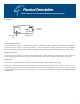
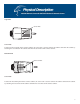
Rear Panel
Network Cable Connector
The rear panel of the wireless network camera features an RJ-45 connector for 10Base-T Ethernet or 100Base-TX Fast
Ethernet connections (using Category 5 twisted-pair cabling). The port supports the N-Way protocol and the “Auto-
MDIX” function, thereby allowing the wireless network camera to automatically detect or negotiate the transmission
speed of the network.
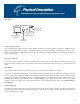
DC Power Connector
The DC power input connector is located on the rear panel of the wireless network camera and is labeled DC 5V with a
single jack socket to supply power to the camera. Power will be generated when the power supply is connected to a wall
outlet.
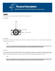
Reset Button
Reset will be initiated when the reset button is pressed once and the “Power” LED begins to flash.
Factory Reset will be initiated when the reset button is pressed continuously for at least three seconds or when the
“Power” LED begins to light up. Release the reset button and the “Power” LED will begin to flash, indicating that the
wireless network camera is utilizing the factory reset. When factory reset is completed the wireless camera will be set to
Channel 11 by default and the ESS-ID is set as “NULL String”. (This default setting will let the wireless camera
connect to ANY access point on the infrastructure network). The IP address will also return to the default setting of
192.168.0.20.
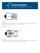
Antenna Connector
The SMA-type antenna connector is located on the rear panel of the wireless camera, thereby providing connection for a
high-sensitivity antenna that is included with the device. The antenna can rotate, thus allowing the user to adjust its
position to obtain the best signal.
Network Cable
Connector
DC Power
Connector
Reset Button
Antenna
Connector
10/100 Ethernet
DC 5V
Reset
ANT