
Owners manual
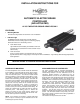
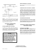
Table Of Contents

INSTALLATION INSTRUCTIONS FOR
AUTOMATIC ELECTRIC BRAKE
CONTROLLER
(AIR ACTUATED)
12 VOLT NEGATIVE GROUND VEHICLES ONLY
FEATURES:
• Mounting Bracket
Universal mounting bracket with screws for ease of installation.
• Indicator Light
The Hayes automatic electric brake controller indicator
will illuminate when the braking system is functioning properly.
Illumination will occur in the following manner:
A. Trailer Disconnected
Light will illuminate immediately to full brilliance when tow
vehicle brakes are activated or the brake controller is actu-
ated manually.
B. Trailer Connected
Under a no-brake situation, the light
will remain off. As brakes are applied (either automatically or manually) the indicator
light will illuminate with a varying degree of intensity from dim to full brilliance. Light intensity will be directly proportional to
brake application.
100400-B
Figure 1.
NOTE: INSTRUCTIONS ARE AVAILABLE TO CONVERT THIS AIR ACTUATED CONTROLLER FROM A
NEGATIVE GROUND TO
A POSITIVE GROUND ELECTRICAL SYSTEM.
CONTROLLER MOUNTING
The mounted position of the control
ler should be determined
by the installer in conjunction with the vehicle owner’s prefer-
ence. The most common position of the controller has been
under the instrument panel. The owner/or installer should
hold the controller in various locations while sitting in a driv-
ing position to determine the most convenient and safest
location. After determining controller location, clean both the
top surface of the controller and the instrument panel mount-
ing area of dirt and grease. Apply double-faced tape to the
contact area of the top surface of the controller and press
into place on instrument panel. Locate “U” bracket over
controller, mark hole location. To assure accurate location, it
is best to center punch the hole locations before drilling. Be
careful not to drill through any wiring that may be under the
instrument panel. After drilling, place “U” bracket into
position and insert the two screws through bracket and
instrument panel and securely tighten with Tinnerman nuts.
Do not use the tape alone for mounting.
NOTE: If the controller is mounted to a plastic instrument
panel, it may be necessary to ground controller case for the
indicator light to operate correctly.
AIR CONNECTION OF CONTROLLER
The Hayes controller may be operated automatically or
manually. Automatic operation is strongly recommended for
normal driving because it is more convenient and, in an
emergency stopping situation, it is difficult for even an
experienced driver to reach for the control handle, operate
the brake pedal, and coordinate the tow vehicle for maximum
braking effect. For automatic operation, the cylinder on the
controller must be connected into the air brake system of the
tow vehicle. This connection is made by installing a 3/16” or
1/4” diameter S.A.E. approved tubing from the brake
controller to the vehicle service line. For brake systems with
primary and secondary service lines, connect a two-way
check valve between the two service lines and install the
tubing from the output side of the check valve to the brake
controller. The two-way check valve should be located
between the treadle valve and before any other valves in the
system. This will retain isolation of the primary and secon-
dary service system and allow trailer braking capabilities if
either system should fail.
The controller air inlet port thread is 1/8” NPT.