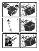
3/30 HERITAGE TRACTOR CODE 131E INSTRUCTION BOOK CODE SERIAL NO. 131E 270000001 ISSUE 01/22/07 1740520 PART NO: 111-1012 (rev.A.
1 5 (30x49) 6 1 4 (17x195) 2 7 (17x192) 3 5 (1001054) 3 4 (17x47) 1 2 3 7 7 (14x79) 4 4 5 4 (25x3) 2 8 6 (2x82) 6 (17x146) 1 6 (2x82) 3 1 3 2 6 6 (1x121) 3 10 5 6 1 7 (15x116) 3 5 6 (1x121) 4 4 6 (1x121) 7 (15x116) 5 6 (1x121) 9 2 7 (15x116) 1740520 2 8
11 7 8 8 9 10 3 14 3 9 9 10 9 13 12 15 11 9 1 2 1740520 3 12
13 14 1 1 7 2 2 6 4 3 5 1 15 2 16 1 2 3 7 8 17 18 6 3 4 5 9 1740520 4
19 20 6 1 7 10 5 2 8 1 2 9 4 3 1 21 5 7 22 4 1 3 1 4 5 2 3 2 23 24 1 8 6 4 3 2 5 7 1 3 1740520 5 2
25 2 2 26 1 1 2 1 27 1 3 4 28 29 1 2 1740520 6 2
30 31 3 6 1 2 3 2 4 1 5 33 32 4 2 1 3 2 3 1 34 35 1 1 1 1740520 7
36 8 2 1 4 1 1 3 6 4 3 5 7 1740520 8 9
37 1 2 3 9 8 MAX + 90N 10 7 6 5 4 MAX + 150N 11 12 14 13 38 1 10 2 4 3 11 12 5 6 7 13 14 15 8 9 39 2x82 14x79 15x116 30x49 25x3 20729 1x121 17x146 17x195 1001054 17x192 17x47 1740520 9
GB LIMITED WARRANTY Hayter Limited warrants to the original user / purchaser that this unit shall be free from defects in material and workmanship under normal use and service for a period of three years from the date of purchase. The manufacturers of the engine and battery pack system (where applicable) furnish their own warranty and services are provided through their authorised network (Refer to “Engine/Battery Pack Warranty Statement”).
GB CONTENTS LIMITED WARRANTY 10 INTERNATIONAL PICTORIALS 11 OWNER’S INFORMATION 12 SAFE OPERATION PRACTICES 12 ASSEMBLY 13 OPERATION 14 MAINTENANCE 15 TROUBLE SHOOTING CHART 19 INTERNATIONAL PICTORIALS IMPORTANT: The following pictorials are located on your unit or on literature supplied with the product. Before you operate the unit, learn and understand the purpose for each pictorial. NOTE: Illustrations and pictorials begin on page 2.
OWNER’S INFORMATION Know your product: If you understand the unit and how the unit operates, you will get the best performance. As you read this manual, compare the illustrations to the unit. Learn the location and the function of the controls. To help prevent an accident, follow the operating instructions and the safety rules. Keep this manual for future reference. GB 2. 3. WARNING: Look for this symbol to indicate important safety precautions.
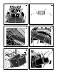
ASSEMBLY All fasteners are in the parts bag. Do not discard any parts or material until the unit is assembled. WARNING: Before doing any assembly or maintenance to the mower, remove the wire from the spark plug. NOTE: In this instruction book, left and right describe the location of a part with the operator on the seat. NOTE: Illustrations and pictorials begin on page 2. NOTE: To assemble the following loose parts, use the fasteners shown at full size in Figure 39.
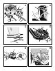
OPERATION NOTE: Illustrations and pictorials begin on page 2. Location Of Controls (Figure 13) Blade Rotation Control (1): Use the blade rotation control to start and stop the rotation of the blade. Clutch / Brake Pedal (2): The pedal has two functions. The first function is a clutch. The second function is a brake. Headlight Switch (3): The headlight switch is the first part of the ignition switch. To use the lights with the engine running, turn the key to the position for the lights.
GB 3. To start again, make sure the shift lever is in the slowest speed. Move the throttle control to the SLOW position. Slowly release the pedal. Before Starting The Engine 6. Slowly move the throttle control to the SLOW position. Check the oil 4. If you must stop or start on a hill, always have enough space for the unit to roll when you release the brake and engage the clutch. NOTE: The engine was shipped from the factory filled with oil. Check the level of the oil. Add oil as needed.
To Remove 1. Move the blade rotation control to the DISENGAGE position. 2. Move the shift lever to the neutral (N) position. 3. Engage the parking brake. 4. Stop the engine. 5. Move the lift lever to the middle cutting position. GB 5. Check the blade (1) and the blade adapter (5) according to the instructions for “Inspect Blade”. Check the air assist fan (8) for damage. Replace badly worn or damaged parts with original equipment parts. See an authorized service centre in your area. 6.
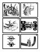
3. Disconnect the adjustable nut (4) from the brake lever assembly (5) and the parking brake latch (6). 4. Align the hole in the brake lever (5) with the hole in the frame. Hold the brake lever (5) in place with a 6 mm pin or bolt (7). 5. Pull the clutch rod forward until tight. Turn the adjustable nut (4) until the nut will fit through the hole in the brake lever (5). 6. Assemble the adjustable nut (4) to the parking brake latch (6), brake lever (5) and brake spring (3).
5. Before you mow, check the blade rotation control. See the instructions on “How to Adjust The Blade Rotation Control”. How To Remove The Mower Housing (Figure 36) 1. Move the blade rotation control (1) to the DISENGAGE position. 2. Move the lift lever (2) to the lowest position. WARNING: The lift lever (2) is spring loaded. Make sure the lift lever (2) is locked in the lowest position. 3. Remove the hair pins and the washers from the adjuster arms (3). See illustrations “C” and “D”. 4.
TROUBLE SHOOTING CHART GB 4. Replace the fuel filter. 7. Clean the extension tube and the connector tube (applies only to model with rear discharge grass bag). 1. Follow the steps, “How To Start The Engine” in this book. PROBLEM: The engine stops when the blades are engaged. PROBLEM: The mower housing does not cut level. 2. Electric--Start Models: Clean the battery terminals. Tighten the cables. 1. Check the wiring harness for damage or a loose connection. Repair the damaged wire. 3.
1740520 20