POWERTRIM Code 407F OWNER’S HANDBOOK CODE SERIAL NO. 407F 310000001 Issue 10/2009 PART NO: 111-3445 (Rev.
TABLE OF CONTENTS 3 4 8 11 14 19 21 23 LIMITED WARRANTY OPERATOR SAFETY ASSEMBLY OPERATION MAINTENANCE TROUBLESHOOTING SPECIFICATIONS REPAIR PARTS 1739579 2
LIMITED WARRANTY Hayter Limited warrants to the original user / purchaser that this unit shall be free from defects in material and workmanship under normal use and service for a period of three years from the date of purchase. The manufacturers of the engine and battery pack system (where applicable) furnish their own warranty and services are provided through their authorised network (Refer to “Engine/Battery Pack Warranty Statement”).
OPERATOR SAFETY OWNER’S INFORMATION 7. Know your product: If you understand the unit and how the unit operates, you will get the best performance. As you read this manual, compare the illustrations to the unit. Learn the location and the function of the controls. It is important that you read and understand these original instructions thoroughly before attempting to start or operate this equipment. 8. 9. 10. WARNING: Look for this symbol to indicate important safety precautions.
OPERATOR SAFETY Do not trim on wet grass. Reduced footing could cause slipping. 21. Stop the engine whenever you leave the equipment, before cleaning repairing or inspecting the unit, be sure the trimmer head and all moving parts have stopped. Let the engine cool, disconnect the spark plug wire and move it away from the spark plug. 22. If the equipment should start to vibrate abnormally, stop the engine, disconnect the spark plug wire and prevent it from touching the spark plug.
OPERATOR SAFETY 2. 3. 4. 5. 6. 7. Never run the engine indoors or inside a closed area. The exhaust fumes are dangerous, containing CARBON MONOXIDE, an ODORLESS and DEADLY gas. Never make adjustments or repairs with the engine running. Disconnect the spark plug wire, and keep the wire away from the plug to prevent accidental starting. Always wear eye protection when you make adjustments or repairs. Check the trimmer head and engine mounting bolts at frequent intervals for proper tightness.
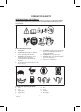
OPERATOR SAFETY INTERNATIONAL PICTORIALS IMPORTANT: The following pictorials are located on your unit or on literature supplied with the product. Before you operate the unit, learn and understand the purpose for each pictorial. 1 2 6 5 4 3 7 8 Safety Warning Pictorials 1 WARNING 2 IMPORTANT: Read Owner’s Manual Before Operating This Machine. 3 WARNING: Thrown Objects. Keep Bystanders Away. Read User Instructions Before Operating This Machine. 4 5 6 7 8 WARNING: Rotating Parts.
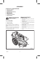
ASSEMBLY CONTENTS OF LITERATURE PACK 1 - Operator’s Manual 1 - Engine Manual 1 - Document of Conformity 1 - Warranty Card 1 - Safety Glasses 1 - Trimmer Line (2 Sets) 1 - Bag (4 Screws) REMOVE THE TRIMMER FROM CARTON WARNING: Always wear safety glasses or eye shields while assembling the machine. 1. Remove the parts bag and any loose parts from carton. 2. Remove the packing material positioned around the unit. 3. Cut down all four corners of the carton and lay the side panels flat. 4.
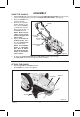
RAISE THE HANDLE ASSEMBLY 1. Hold the handle with one hand and loosen both handle adjustment knobs until the ratchet teeth are disengaged. Do not remove the handle adjustment knobs. See Figure 2. 2. Raise the handle to the operating position. 3. Stand in the operator’s Handle position behind the machine. Put the handle in a comfortable position. Rope Make sure both sides of Guide the handle are level. NOTE: Make sure the cables are not caught Recoil Start between the upper and Handle lower handle.
ENGINE PREPARATION ASSEMBLY Fill Crankcase With Oil 1. Remove the oil fill cap/dipstick shown in Figure 4. Fill the crankcase to the FULL line on oil fill cap/dipstick. DO NOT OVERFILL. 2. Install the oil fill cap/dipstick and tighten securely. Note: Engine does not contain OIL or PETROL. WARNING: Follow the engine manufacturer’s instructions for the type of petrol and oil to use. Always use a safety petrol container. Do not smoke when adding petrol to the engine.
OPERATION KNOW YOUR POWERTRIM READ THE OWNER’S HANDBOOK AND ALL SAFETY RULES BEFORE YOU OPERATE the machine. To familiarise yourself with the location of the controls, compare the illustrations with your machine. Save this handbook for future reference.
USE THE TRIMMER HEAD DRIVE LEVER OPERATION Control Bail Handlebar 1. To engage the trimmer head, hold the control bail against the handle. Move the trimmer head drive lever forward to engage the trimmer head. See Figure 6. The faster the engine runs, the faster the trimmer head will rotate. 2. Once the trimmer head is rotating, push the machine forward to trim. Trimmer Head Drive Lever Figure 6 USE THE THROTTLE CONTROL 1.
START THE ENGINE OPERATION NOTE: If engine fails to start after three pulls, push the primer button two times and again pull the recoil starter handle. NOTE: DO NOT BE ALARMED, your engine will smoke the first time it is started. It is burning off the protective coating that is on the internal engine parts. WARNING: Never run the engine indoors or in a poorly ventilated area. Engine exhaust contains carbon monoxide, an odorless and deadly gas.
MAINTENANCE SERVICE RECORDS Fill in dates as you complete regular service. Check Engine Oil Level Before Each Use Every 5 Hours Every 25 Hours Every 100 Hours As Noted √ Check Trimmer Lines √ Check Trimmer Head Engagement √ Engine/Machine Cleaning √ Check Nuts and Bolts √ 1 2 √ Check Spark Plug Change Engine Oil √ Service Air Filter √ Lubricate Jackshaft Assembly √ Lubricate Wheel Bearings √ Note 1 − When old line is half the original length, replace with new line.
MAINTENANCE LUBRICATION Grease Fitting Lubricate the Jackshaft Assembly A grease fitting is provided to lubricate the jackshaft assembly. Use a grease gun with automotive type grease to lubricate the jackshaft assembly as shown in Figure 10. Figure 10 Change Engine Oil 7. Connect the spark plug wire to the spark plug. Change the engine oil when the engine is warm. For the proper oil capacity, see the engine manufacturer’s instructions. 1. Disconnect spark plug wire from the spark plug.
MAINTENANCE SPARK PLUG Check the spark plug every 25 hours. Replace the spark plug if the electrodes are pitted or burned or if the porcelain is cracked. 1. Tighten the spark plug to a torque of 15 foot−pounds. Make sure the spark plug is clean. Clean the spark plug by carefully scraping the electrodes (do not sand blast or use a wire brush). Feeler Gauge 0.030” 2. Check the spark plug gap with a feeler gauge. See “Product Specifications” for the correct spark plug gap and replacement spark plug.
MAINTENANCE SERVICE AND ADJUSTMENT WARNING: Before you inspect, clean or service the machine, stop the engine. Make sure that all moving parts have stopped. Disconnect the wire from the spark plug. PROPER CARE OF TRIMMER LINE IMPORTANT: To extend the life of the trimmer line, keep the trimmer line moist. If not kept moist, the nylon trimmer line will become dry and brittle. Keep extra trimmer line in a can of water. The line will then stay flexible and easy to change.
MAINTENANCE REPLACE THE DRIVE BELT To replace the drive belt, see an authorized service center. STORAGE Engine WARNING: Do not remove petrol while inside a building, near a fire, or while you smoke. Petrol fumes can cause an explosion or a fire. To prevent engine damage when the machine is in storage for 30 days or more, follow the steps below: Let the engine run until it is out of petrol.
TROUBLESHOOTING CHART TROUBLE CAUSE CORRECTION Engine does not start. Spark plug wire disconnected. Connect spark plug wire. Engine not primed. Prime engine. Defective or incorrectly gapped spark plug. Inspect or replace spark plug. Fuel tank empty. Add fuel. Dirty carburetor or fuel line. Clean carburetor or fuel line. Dirty air filter. Replace air filter. Carburetor out of adjustment. See authorized dealer. Engine flooded. Wait several minutes before starting.
TROUBLESHOOTING CHART Engine overheats. Engine cooling system clogged. See authorized dealer. Carburetor out of adjustment. See authorized dealer. Oil level is low. Add oil. Engine will not stop running. Defective throttle control lever or wire. See authorized dealer. Poor trimming performance. Trimmer line length is too short. Correct line length is 52 cm (21,5 inches). When less than 1/2 this length, replace the line. Trimmer vibrates. Engine not set at FAST speed.
SPECIFICATIONS Trimmer Line Diameter 3,9 mm (0,155”) Trimmer Line Length 520 mm (21,5”) Height of Cut (Fixed) 76 mm (3”) Dimensions 1400 x 555 x 1000 Engine Briggs 122T02-0188-B1 KW 2,56 Displacement 190 cc (11,57 cu in.) Petrol Capacity 0,95 L (1,0 quarts) Oil Capacity 0,54 - 0,59 L (18-20 oz) Spark Plug Champion RJ−19LM Spark Plug Gap 0,76 mm (0.030 in.
Order Replacement Parts Replacement parts, except for the engine, transmission, transaxle or differential, are available from your local Hayter authorised dealer, the store where the mower was purchased or a service shop recommended by the store. If you are unable to obtain parts or service in the manner outlined above, then contact: HAYTER LIMITED, Service Department, Spellbrook, Bishop’s Stortford, Hertfordshire.
Repair Parts PTS - 1
Handle And Wheels POWERTRIM Code 407F NOTE: Unless noted otherwise, use the standard hardware torque specification chart.
Handle And Wheels REF NO PART NO.
Cutting Head And Shield POWERTRIM Code 407F NOTE: Unless noted otherwise, use the standard hardware torque specification chart.
Cutting Head And Shield REF NO PART NO. 1 2 3 4 5 6 7 8 9 10 11 12 13 14 15 16 17 18 19 20 22 23 24 25 26 27 29 30 31 33 MU015X84MA MU025X11MA MU740150E701MA MU26X256MA MU740232MA MU009X48MA MU712403MA MU740292MA MU15X119MA M710083MA MU740171MA MU740173MA MU711933MA MU740244MA MU740179MA MU740183MA MU018X31MA MU001X20MA MU26X235MA MU770070MA MU740206MA MU26X294MA MU1001049MA MU740300MA MU740163MA MU712126MA MU770037MA MU712127MA MU740165MA MU740299MA QTY.
Hardware Identification & Torque Specifications Common Hardware Types Torque Specification Chart Hex Head Capscrew FOR STANDARD MACHINE HARDWARE (Tolerance ± 20%) Washer Hardware Grade Lockwasher Carriage Bolt No Marks SAE Grade 2 Hex Nut Size Of Hardware Standard Hardware Sizing 8-32 8-36 10-24 10-32 1/4-20 1/4-28 5/16-18 5/16-24 3/8-16 3/8-24 7/16-14 7/16-20 1/2-13 1/2-20 9/16-12 9/16-18 5/8-11 5/8-18 3/4-10 3/4-16 7/8-9 7/8-14 1-8 1-12 When a washer or nut is identified as 1/2”, this is the