
Swimming Pool Pump User Manual


®
P/N-IS3200-HC-07
OWNER’S MANUAL
INSTALLATION, OPERATION, & PARTS
TriStar Pump Series
™
The Hayward TriStar Pump is Specifically Engineered for the demanding requirements of today’s in-ground
swimming pool/spa that is equipped with large capacity filters, heaters, and pool cleaning equipment. The
TriStar is a self-priming pump that incorporates an improved seal and impeller design that will provide many
years of efficient, dependable, corrosion-free service. The advanced design provides superior performance
while reducing maintenance requirements. NOTE - To prevent potential injury and to avoid unnecessary
service calls, read this manual carefully and completely.
IMPORTANT - READ CAREFULLY
NOTE - The TriStar is a high performance, high efficiency
pump. When replacing most existing pumps, you can use a
TriStar pump with a lower horsepower rating than the
existing pump. Required: 2” Plumbing minimum.
SAVE THIS INSTRUCTION MANUAL
HAYWARD POOL PRODUCTS CANADA INC.
2880 Plymouth Drive, Oakville, ON L6H 5R4
TEL: (905) 829-2880
WWW.HAYWARDCANADA.COM USE ONLY HAYWARD GENUINE REPLACEMENT PARTS
TriStar Pump Series Page 2 of 8
™
WARNING -- This product should be installed and serviced only by a qualified professional.
CAUTION -- A Licensed electrician MUST complete, in full, all electrical installations noted in this manual.
Use of non-Hayward replacement parts voids warranty.
ATTENTION INSTALLER - THIS MANUAL CONTAINS IMPORTANT INFORMATION ABOUT THE INSTALLATION,
OPERATION, AND SAFE USE OF THIS PUMP THAT MUST BE FURNISHED TO THE END USER OF THIS PRODUCT.
FAILURE TO READ AND FOLLOW ALL INSTRUCTIONS COULD RESULT IN SERIOUS INJURY.
WARNING - Read and follow all instructions in this
owner’s manual and on the equipment. Failure to follow
instructions can cause severe injury and/or death.
IMPORTANT SAFETY INSTRUCTIONS
Before installing or servicing this electrical equipment, turn power supply OFF.
Basic safety percautions should always be followed, including the following: Failure to follow instructions may result in injury.
This is the safety-alert symbol. When you see this symbol on your pump or in this manual, look for one of the following
signal words and be alert to the potential for personal injury.
DANGER warns about hazards that will cause serious potential injury, death or major property damage and if
ignored presents an imminent hazard.
WARNING warns about hazards that could cause serious personal injury, death or major property damage and if
ignored presents a potential hazard.
CAUTION warns about hazards that will or can cause minor or moderate personal injury and/or property damage
and if ignored presents a potential hazard. It can also make consumers aware of actions that are unpredictable and unsafe.
The NOTICE label indicated special instructions that are important but not related to hazards.
WARNING - To reduce risk of injury, do not permit children to use or climb on this product. Closely supervise
children at all times. Components such as the filtration system, pumps, and heaters must be positioned to prevent children
from using them as means of access to the pool.
CAUTION - This pump is intended for use on permanently installed swimming pools and may also be used with
hot tubs and spas if so marked. Do NOT use with storable pools. A permanently installed pool is constructed in or on the
ground or in a building such that it cannot be readily disassembled for storage. A storable pool is constructed so that it is
capable of being readily disassembled for storage and reassembled to its original integrity. Though this product is designed for
outdoor use, it is strongly advised to protect the electrical components from the weather. Select a well-drained area, one that
will not flood when it rains. It requires free circulation of air for cooling. Do not install in a damp or non-ventilated location. If
installed within an outer enclosure or beneath a skirt of a hot tub or spa, adequate ventilation and free circulation of air must
be provided to prevent overheating of the motor.
WARNING - Pool and spa components have a finite life. All components should be inspected frequently and
replaced at least every ten years, or if found to be damaged, broken, cracked, missing, or not securely attached.
WWW.HAYWARDCANADA.COM USE ONLY HAYWARD GENUINE REPLACEMENT PARTS
TriStar Pump Series Page 3 of 8
™
WWW.HAYWARDCANADA.COM USE ONLY HAYWARD GENUINE REPLACEMENT PARTS
WARNING - Risk of Electrical Shock. It is required that licensed electricians do all the
electrical wiring. Hazardous voltage. Can shock, burn, or cause death. To reduce the risk of electrical shock, do
NOT use an extension cord to connect unit to electric supply. Provide properly located outlet. All electrical wiring
MUST be in conformance with applicable local and national codes and regulations. Before working on pump or
motor, disconnect motor wiring.
WARNING - To reduce the risk of electrical shock replace damaged cord immediately. Do NOT bury cord. Locate cord to
prevent abuse from lawn mowers, hedge trimmers and other equipment.
WARNING - Connect only to a grounding type receptacle protected by a Ground Fault Circuit Interrupter (GFCI).
Contact a licensed electrician if you cannot verify that the receptacle is protected by a GFCI.
WARNING - Failure to bond pump to pool structure will increase risk of electrocution and could result in injury or death. To
reduce the risk of electrical shock, see installation instructions and consult a professional electrician on how to bond pump. Also, contact a
licensed electrician for information on local electrical codes for bonding requirements.
Use a solid copper conductor, size 6 or larger. Run continuous wire from external bonding lug to reinforcing rod or mesh. Connect a No. 6
AWG solid copper bonding wire to the pressure wire connector provided on the motor housing and to all metal parts of swimming pool, spa,
or hot tub, and to all the electrical equipment, metal piping (except gas piping), and conduit within 5 ft. (1.5 m) of inside walls of swimming
pool, spa, or hot tub. IMPORTANT - Reference Canadian Electrical Codes for all wiring standards including, but not limited to grounding,
bonding and other general wiring procedures.
WARNING - Suction Entrapment Hazard.
Suction in suction outlets and/or suction outlet covers which are damaged, broken, cracked, missing, or
unsecured cause sever injury and/or death due to the following entrapment hazards:
Hair Entrapment - Hair can become entangled in suction outlet cover.
Limb Entrapment - A limb inserted into an opening of a section outlet sump or suction outlet cover that is
damaged, broken, cracked, missing, or not securely attached can result in a medical bind or swelling of the
limb.
Body Suction Entrapment - A differential pressure applied to a large portion of the body or limbs can result in an entrapment.
Evisceration/Disembowelment - A negative pressure applied directly to the intestines through an unprotected suction outlet
sump or suction outlet cover which is damaged, broken, cracked, missing, or unsecured can result in
evisceration/disembowelment.
Mechanical Entrapment - There is potential for jewelry, swimsuits, hair decorations, fingers, toes, or knuckles to be caught in
an opening of a suction outlet cover resulting in mechanical entrapment.
WARNING - To Reduce the risk of Entrapment Hazards:
- When outlets are small enough to be blocked by a person, a minimum of two functioning suction outlets per
pump must be installed. Suction outlets in the same place (i.e. floor or wall), must be installed a minimum of
three feet (3’) [0.91 meter] apart, as measured from near point to near point.
- Dual suction fittings shall be placed in such locations and distanced to avoid “dual blockage” by a user.
- Dual suction fittings shall not be located on seating areas or on the backrest for such seating areas.
- The maximum system flow rate shall not exceed the values shown in the “Pipe Sizing Chart” found at the bottom of page 4 of this manual
- Never use pool or spa if any suction outlet component is damaged, broken, cracked, missing, or not securely attached.
- Replace damaged, broken, cracked, missing, or not securely attached suction outlet components immediately.
- In addition to two or more suction outlets per pump installed in accordance with the latest IAF (formerly NSPI) standards and CPSC
guidelines, follow all national, state, and local codes applicable.
- Installation of a vacuum release or vent system, which relieves entrapping suction, is recommended.
TriStar Pump Series Page 4 of 8
™
WWW.HAYWARDCANADA.COM USE ONLY HAYWARD GENUINE REPLACEMENT PARTS
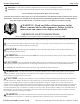
8.43
10.18
“A”
13.61
8.16
11.53
7.63
8.74
Product Specifications
HP Rating
3/4
1
1 1/2
2
3
12-3/32”
Length “A”
12-19/32”
13-3/32”
13-3/32”
15-3/32”
Installation Instuctions
WARNING - This product should be installed and serviced only by a qualified professional.
Pump Location
Locate pump as close to pool as practical and run suction lines as direct as possible to reduce friction loss.
Suction lines should have continuous slope upwards from lowest point in line. Joints must be tight (but not
over-tightened). Suction line diameter must equal or be larger than the discharge diameter.
Though the pump is designed for outdoor use, it is strongly advised to protect the electrical components
from the weather. Select a well-drained area, one that will not flood when it rains. Do NOT install pump in a damp or
non-ventilated location. Keep motor clean. Pump motors require free circulation from air for cooling.
Pump Mounting
Install pump on a firm, level base or pad to meet all local and national codes. Fasten pump to base or pad with screws or bolts to
further reduce vibration and stress on pipe or hose joints. The base MUST be solid, level, rigid, and vibration free.
Pump mount must:
Allow pump inlet height to be as close to water level as possible.
Allow use of short, direct suction pipe (to reduce friction losses).
Allow for gate valves in suction and discharge piping.
Be protected from excess moisture and flooding.
Allow adequate access for servicing pump and piping.
Pipe Sizing Chart
NOTE - It is recommended that a minimum length of piping, equivalent to 10 pipe diameters, be used between the
pump suction inlet and any plumbing fittings.
Pipe Size
[mm]
Flow Rate
GPM [L PM]
Suction Pipe
Length *
Pipe Size
[mm]
Flow Rate
GPM [L PM]
Suction Pipe
Length *
Pipe Size
[mm]
Flow Rate
GPM [L PM]
Suction Pipe
Length *
1” [32]
20 [75]
5”
1 ½” [50]
45 [170]
7 ½”
2 ½” [75]
110 [415]
12 ½”
1 ¼” [40]
30 [110]
6 ¼”
2” [63]
80 [300]
10”
3” [90]
160 [600]
15”
M AX I M UM R E C OM M E NDE D SY ST E M F L OW R AT E B Y PI PE SI ZE
TriStar Pump Series Page 5 of 8
™
WWW.HAYWARDCANADA.COM USE ONLY HAYWARD GENUINE REPLACEMENT PARTS
WARNING
- Hazardous Pressure. Pumps, filters, and other equipment/components of a swimming pool
filtration system operate under pressure. Incorrectly installed and/or improperly tested filtration equipment and/or components
may fail resulting in injury and/or property damage.
Pump Mounting (cont’d.)
Plumbing
Use Teflon tape to seal threaded connections on molded plastic components. All plastic fittings must be new or thoroughly cleaned before
use. NOTE - Do NOT use Plumber’s Pipe Dope as it may cause cracking to the plastic components. When applying Teflon tape to
plastic threads, wrap the entire threaded portion of the male fitting with one to two layers of tape. Wind the tape clockwise as you face the
open end of the fitting, beginning at the end of the fitting. The pump suction and outlet ports have molded-in thread stops. Do NOT attempt
to force hose connector fitting past this stop. It is only necessary to tighten fittings enough to prevent leakage. Tighten fitting by hand and
then use a tool to engage fitting an additional 1 ½ turns. Use care when using Teflon tape as friction is reduced considerable; do NOT
over-tighten fitting or you may cause damage. If leaks occur, remove connector, clean off old Teflon tape, re-wrap with one or two
additional layers of Teflon tape, and re-install connector.
Fittings
Fittings restrict flow. For better efficiency, use the fewest possible fittings (but at least two suction outlets). Avoid fittings that could cause
an air trap. Pool and spa fittings MUST conform to the International Association of Plumping and Mechanical Officials (IAPMO)
standards. Use a non-entrapping suction fitting in pool (multiple drains) or double suction (skimmer and main drain).
Electrical
WARNING
- Ground and bond motor before connecting to electrical power supply. Failure to ground and
bond pump motor can cause serious or fatal electrical shock hazard.
WARNING
- Do NOT ground to a gas supply line.
WARNING
- To avoid dangerous or fatal electrical shock, turn OFF power to motor before working on
electrical connections.
WARNING
- Ground Fault Circuit Interrupter (GFCI) tripping indicates electrical problem. If GFCI trips and
wont reset, consult electrician to inspect and repair electrical system.
WARNING
- Fire Hazard. Match supply voltage to motor nameplate voltage.
Insure that the electrical supply available agrees with the motor’s voltage, phase, and cycle, and that the wire size is adequate for the H.P.
(KW) rating and distance from the power source. NOTE - All electrical wiring MUST be performed by a licensed electrician, and
MUST conform to local codes and Canadian Electrical Code regulations. Use copper conductors only.
Motor Specifications
M otor Br ake H orsepower
M otor Rated H or sepower
M otor E lectric V /A
W ir e Size / B r eaker
H P ( kW )
H P ( kW )
V oltage
A mps
A W G
A mps
1.13 (0.84)
0.50 (0.37)
208 - 230 / 115
5.3 - 4.9 / 9.8
14
10 / 15
1.39 (1.04)
0.75 (0.56)
208 - 230 / 115
7.0 - 6.2 / 12.4
14
10 / 15
1.85 (1.38)
1.00 (0.75)
208 - 230 / 115
8.5 - 7.4 / 14.8
14 / 12
15 / 20
2.40 (1.79)
1.50 (1.12)
208 - 230 / 115
11.2 - 10.2 / 20.4
14 / 10
15 / 30
2.70 (2.01)
2.00 (1.49)
208 - 230
11.8 - 11.0
14
15
3.60 (2.69)
3.00 (2.24)
208 - 230
16.0 - 14.8
12
20
3.60 (2.69) *
3.00 (2.24) *
208 - 230 / 460 *
9.6 - 9.4 / 4.7 *
14 *
15 / 10 *
1.85 / 0.22 (1.38 / 0.16)
1.00 / 0.12 (0.75 / 0.09)
208 - 230
8.6 - 8.2
14
15
2.40 / 0.28 (1.79 / 0.21)
1.50 / 0.18 (1.12 / 0.13)
208 - 230
11.4 - 10.4
14
15
F ull R ate Pumps
2.70 / 0.33 (2.01 / 0.25)
2.00 / 0.25 (1.49 / 0.19)
208 - 230
12.4 - 11.2
14
15
0.94 (0.70)
0.75 (0.56)
5.4 / 10.8
14
10 / 15
1.25 (0.93)
1.00 (0.75)
230 / 115
7.0 / 14.0
14
10 / 15
1.65 (1.23)
1.50 (1.12)
230 / 115
7.7 / 15.4
14 / 12
10 / 20
2.20 (1.64)
2.00 (1.49)
230 / 115
10.8 / 21.6
14 / 10
15 / 30
2.60 (1.94)
2.50 (1.86)
230
11.5
14
15
3.45 (2.57)
3.00 (2.24)
230
13.5
14
15
1.85 / 0.22 (1.38 / 0.16)
1.50 / 0.18 (1.12 / 0.13)
208 - 230
8.6 - 8.2
14
15
2.40 / 0.28 (1.79 / 0.21)
2.00 / 0.25 (1.49 / 0.19)
208 - 230
11.4 - 10.4
14
15
M ax R ate Pumps
2.70 / 0.33 (2.01 / 0.25)
2.50 / 0.31 (1.86 / 0.23)
208 - 230
12.4 - 11.2
14
15
,
- - -
- -
¹, ², ³ Low Speed Amps: (¹ 2.8 - 3.0) (² 3.2 - 3.4) (³ 3.8 - 4.1)
* Three-Phase (3Φ) Pump - motor starter required
TriStar Pump Series Page 7 of 8
™
WWW.HAYWARDCANADA.COM USE ONLY HAYWARD GENUINE REPLACEMENT PARTS
16
17
1815
14
13
30C2
12
11
10
7
8
9
20
21
22
6
5
4
3
2
1
19
16
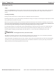
Replacement Parts
Parts Diagram
Parts Listing
Ref. No.
1
2
3
4
5
6
7
8
9
10
11
Part No.
SPX3200UNKIT
SPX3200UG
SPX3200A
SPX3200DLS
SPX3200S
SPX3200M
SPX3200Z8
SPX4000Z1
SPX3200B3
SPX3200Z1
SPX3021R
Description
Union Connector Kit (Nut, Connector, Gasket)
Union Gasket (T-seal), 50 duro EPDM
Pump Strainer Housing, 2” x 2” with Drain Plugs, threaded style
Strainer Cover Kit (Includes Strainer Lexan Cover, Lock Ring, O-Ring)
Strainer Cover O-Ring
Strainer Basket
Diffuser Screw
Diffuser O-Ring
Diffuser, 3 HP
Impeller Screw
Impeller Ring
Ctn. Qty.
1
1
1
10
10
15
1
10
1
1
1
Detail of motor
canopy with screws.
TriStar Pump Series Page 6 of 8
™
WWW.HAYWARDCANADA.COM USE ONLY HAYWARD GENUINE REPLACEMENT PARTS
WARNING
- All wiring must be done by a licensed electrician.
Electrical (cont’d.)
Voltage
Voltage at motor MUST NOT be more than 10% above or below motor name place rated voltage, or motor may overheat, causing overload tripping
and reduced component life. If voltage is less than 90% or more than 110% of rated voltage when motor is running at full load, consult power
company.
Grounding and Bonding
Install, ground, bond, and wire motor is accordance with local or Canadian Electrical Code requirements.
Permanently ground motor. Use green ground terminal provided under motor canopy or access place; use size and type wire required by code. Connect
motor ground terminal to electrical service ground.
Bond motor to pool structure. Bonding will connect all metal parts within and around the pool with a continuous wire. Bonding reduces the risk of a
current passing between bonded metal objects, which could potentially cause electrical shock if grounded or shorted. Reference Canadian Electrical
Codes for all wiring standards including, but not limited to, grounding, bonding and general wiring procedures.
Use a solid copper conductor, size 6 or larger. Run wire from external bonding lug to reinforcing rod or mesh. Connect a No. 6 AWG solid copper
bonding wire to the pressure wire connector provided on the motor housing and to all metal parts of swimming pool, spa, or hot tub, and to all
electrical equipment, metal piping (except gas piping), and conduit within 5 ft. (1.5 m) of inside walls of swimming pool, spa, or hot tub.
Wiring
Pump MUST be permanently connected to circuit. If other lights or appliances are also on the same circuit, be sure to add their amp loads before
calculating wire and circuit breaker sizes. Use the load circuit breaker as the Master On-Off switch,
Install a Ground Fault Circuit Interrupter (GFCI) in circuit; it will sense a short-circuit to ground and disconnect power before it becomes dangerous
to pool users. For size of GFCI required and test procedures for GFCI, see manufacture’s instructions. In case of a power outage, check GFCI for
tripping, which will prevent normal pump operation. Reset if necessary.
TriStar Pump Series Page 8 of 8
™
WWW.HAYWARDCANADA.COM USE ONLY HAYWARD GENUINE REPLACEMENT PARTS
Model No.
Motor P/N
Impeller P/N
SP3207EC
SPX3207Z1BER
SPX3207C
SP3210EC
SPX3210Z1BE
R
SPX3210C
SP3215EC
SPX3215Z1BER
SPX3215C
SP3220EC
SPX3220Z1BER
SPX3220C
SP3230EC
SPX3230Z1BER
SPX3230C
SP32102EC
SPX3210Z2BER
SPX3210C
SP32152E
C
SPX3215Z2BER
SPX3215C
SP32202E
C
SPX3220Z2BER
SPX3220C
Pump SKU Detail
Ref. No.
12
13
14
15
16
17
18
19
20
21 *
22 *
Part No.
SPX3207C
SPX3210C
SPX3215C
SPX3220C
SPX3230C
SPX3200SA
SPX3200T
SPX3200E
SPX3200Z211
SPX3200Z3
SPX3200Z5
SPX4000FG
SPX3200GA
SPX3200WF
SPX3200SR
Description
Impeller for ¾ HP with Impeller Screw
Impeller for 1 HP with Impeller Screw
Impeller for 1 ½ HP with Impeller Screw
Impeller for 2 HP with Impeller Screw
Impeller for 3 HP with Impeller Screw
Shaft Seal Assembly
Housing O-Ring
Seal Plate
Housing Insert & Seal Place Spacer Kit
Housing Bolt
Motor Bolt
Drain Plug with O-Ring
Motor support Bracket
Riser Base, Short
Riser Base, Tall
Ctn. Qty.
10
10
10
10
10
10
10
1
1
10
1
10
1
1
1
Parts Listing (cont’d.)