092538 RevA AquaRite ® Electronic Chlorine Generator Owner’s Manual Contents Operation..............................2 Installation.......................11 Troubleshooting.................. 15 Warranty..............................18 AQR15 AQR9 AQR3 AQR15-120 AQR15-LL Hayward Pool Products 620 Division Street, Elizabeth NJ 07207 www.hayward.
IMPORTANT SAFETY INSTRUCTIONS When using this electrical equipment, basic safety precautions should always be followed, including the following: • READ AND FOLLOW ALL INSTRUCTIONS • Use Copper Conductors Only • Disconnect all AC power during installation. • Warning - To reduce the risk of injury, do not permit children to use this product unless they are closely supervised at all times. • A green colored terminal marked "Earth Ground" is located inside the wiring compartment.
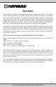
Operation The AquaRite® is an automatic chlorine generation system for pool or spa sanitation. The operation requires a low concentration of salt (sodium chloride) in the pool water. These levels are low enough that it normally will not be tasted. The AquaRite automatically sanitizes your pool by converting the salt into free chlorine which kills bacteria and algae in the pool. Chlorine will revert back to sodium chloride after killing bacteria.
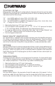
Water Chemistry The table below summarizes the levels that are recommended by The Association of Pool and Spa Professionals (APSP). The only special requirements for the AquaRite are the salt level and stabilizer. It is important to maintain these levels in order to prevent corrosion or scaling and to ensure maximum enjoyment of the pool. Test your water periodically. Your Authorized AquaRite Dealer or most pool stores can provide you with the chemicals and procedures to adjust the water chemistry.
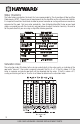
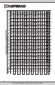
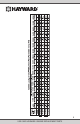
Salt Level Use the chart on page 5 to determine how much salt in pounds or (Kgs) need to be added to reach the recommended levels. Be aware that there may already be salt in your pool from prolonged use of chlorine. Test your pool, then add the correct amount. Use the equations below (measurements are in feet/gallons and meters/liters) if pool size is unknown. Use the equations below (measurements are in feet/gallons and meters/liters) if pool size is unknown.
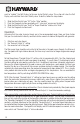
5 USE ONLY HAYWARD GENUINE REPLACEMENT PARTS
6 USE ONLY HAYWARD GENUINE REPLACEMENT PARTS
Controls Main Switch AUTO: For normal operation, the Main Switch should be left in the AUTO position. In this position the AquaRite will produce chlorine according to the "Desired Output %" adjustment setting for the entire filtering/pumping cycle. SUPER CHLORINATE: When you have an abnormally high bather load, a large amount of rain, a cloudy water condition, or any other condition which needs a large amount of purification to be introduced, put the Main Switch in the SUPER CHLORINATE position.
To Set Turbo Cell Type Before operation, the AquaRite must be configured for the chlorinator cell that will be used. Your model AquaRite has been packaged with a corresponding Turbo cell. Refer to the following information and steps below to set the Turbo cell type.
want to "update" the Salt Display to the new Instant Salinity value. This action will clear the Salt Display and substitute the Instant Salinity value. To do this, follow the steps below: 1. 2. 3. 4. Slide the Main Switch from "Off" to the "Auto" position. Push the Diagnostic button repeatedly until "-xxxx ppm" appears on the display. Slide the Main Switch from "Auto" to "Super Chlorinate" and back to "Auto". Push the Diagnostic button to exit.
Maintaining the AquaRite System To maintain maximum performance, it is recommended that you open and visually inspect the cell every 3 months or after cleaning your filter. The AquaRite will remind you to do this by flashing the "Inspect Cell" LED after approximately 500 hours of operation. After you inspect the cell (and clean, if necessary) press the small "diagnostic" button next to the display for 3 seconds to stop the flashing "Inspect Cell" LED and start the timer for the next 500 hours.
Installation Installation must be performed in accordance with Local and NEC codes. AQUA RITE GFCI OUTLET AQR15-120 BOOST AUTO OFF BOOST AUTO OFF G LDLINE CONTROLS INC. FILTER TIMER AQUA RITE 120/240 VAC POWER LINE AQR15-LL AQR15 AQR9 AQR3 BOOST LOAD AUTO OFF BOOST AUTO OFF G SOLAR SYSTEM LDLINE CONTROLS INC.
Plumbing Ensure that the AquaRite installation does not constitute a cross connection with the local potable water supply. Consult local plumbing codes. The AquaRite is packaged with a Turbo cell, flow switch and cell unions. Refer to page 2 for information about available AquaRite models. The flow switch and cell should be plumbed in the return line to the pool/spa. The preferred installation is after (downstream) all the pool equipment (filter, heater, solar, etc.).
Wiring Power must be shut off at the circuit breaker before performing any wiring. Be sure to follow Local and NEC electrical codes. To provide safe operation, the AquaRite must be properly grounded and bonded. Input power for stand alone operation: AQR15, AQR9, AQR3 - Wire the AquaRite to the LOAD SIDE of the filter pump timer. Refer to the wiring label on the AquaRite as well as the diagram below to determine correct wiring connections.
must be open to access the cell cable connector. The flow switch plugs into a connector (similar to a telephone jack) located outside, on the bottom of the enclosure. Refer to the diagram below for the location of these connections. Flow switch connector Cutout for cell cable Bonding lug to pool bonding system Input power for use with Hayward, Pentair and Polaris controls AQR15, AQR9, AQR3 - Wire the AquaRite directly to 120/240VAC power (not through timer or relay).
Hayward - Attach wires to proper screw terminals as shown below. Pentair - Attach wires to opposite numbered screw terminals as shown below. Note that the colors marked on the Pentair PCB do not match the AquaRite. Polaris - Attach wires to proper screw terminals as shown below. Note that screw terminal "1" is marked on the Polaris PCB. Troubleshooting Visit www.hayward.com for helpful information on operation, maintenance and troubleshooting your AquaRite Electronic Chlorine Generator.
2. "Generating" LED flashing The temperature of the pool water is too high or low to operate. You can override this by switching the main switch to SUPER CHLORINATE. The AquaRite will run at maximum output for the remainder of the current pump cycle or 24 hours, whichever comes first. 3. "No Flow" LED illuminated The AquaRite has sensed a no flow condition and has stopped generating chlorine.
- Desired Output % adjustment setting is too low. Low stabilizer (Cyanuric Acid). Filter pump time too short (8 hours for average size pools, more for large pools) Salt level too low (below 2400 ppm, Check Salt LED on). Salt level too high (High Salt LED on). Very warm pools increase chlorine demand--increase Output %, or filter run time. Cold water (below 50ºF) causes AquaRite to stop generating (Generating LED flashing). Excessive scaling on cell. High level of Nitrogen in pool water.
LIMITED WARRANTY (effective 03/01/12) Hayward warrants its Pro Logic, OnCommand and E-Command pool automation products as well as its AquaRite, AquaRite Pro, Aqua Plus and SwimPure chlorination products to be free of defects in materials and workmanship, under normal use and service, for a period of three (3) years. Hayward also warrants its Aqua Trol chlorination products to be free of defects in materials and workmanship, under normal use and service for a period of one (1) year.
ELECTROLYTIC CHLORINE GENERATOR BASIC POOL MAINTENANCE REQUIREMENTS QUARTTERLY MONTHLY WEEKLY TEST IDEAL RANGE ADJUSTMENT REQUIRED Raise desired output % to Free Chlorine 1.0 - 3.0 ppm increase, lower desired output % to decrease -OR- increase or decrease pump filtration time. pH 7.2 - 7.8 Too high - add muriatic acid Too low - add soda ash. Alkalinity 80 - 120 ppm Add baking soda to increase. Add acid as required to decrease.